| Model: | GJQ(X)-DF |
|---|---|
| Brand: | Liwei |
| Origin: | Made In China |
| Category: | Industrial Supplies / Metallurgy Machinery |
| Label: | Flanged , Flexible Rubber Bell , Expansion Joint |
| Price: |
US $2.5
/ pc
|
| Min. Order: | 1 pc |
| Last Online:06 Apr, 2015 |
Product Performance:
a) Structure: Rubber expansion joint is the soft joint of metal pipes, and consists of inner rubber, nylon cord fabric, outer rubber and metal lap joint flanges.
b) Technology: We introduce advanced technology from abroad, and combine it with Chinese manufacture experience. In the manufacturing process, the inner side endures high pressure; nylon cord fabrics and the inner rubber are better combined and can work under higher pressure than normal flexible rubber expansion joint.
c) Features: The inner adhesive layer united perfectly, bright, clean and seamless; the tag adopts the vulcanization process, perfectly matches the product. The products endure high pressure, maintain good elasticity, make large displacement to balance pipe deviation, absorb vibration, make less noise and have easy installation, etc.
Application Range:
a) Application: Rubber expansion joint is widely used in the pipe systems for water supply, drainage, circulating water, HVAC, fire protection, paper making, pharmacy, petroleum chemical industry, ship piping system, water pump, compressor and fan etc.
b) Applicable Media: The normal type is used to transport air ranges from - 15 °C to 115 °C, compressed air, water, sea water, oil, acid and alkali etc. The special type is used to transport the media above ranges from - 30 °C to 250 °C, oil or strong alkali, strong acid and solid material.
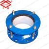
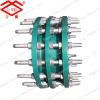
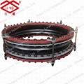
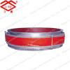
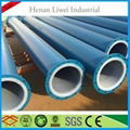
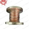
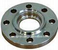
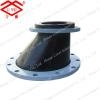
This is the picture of Rubber Joints produced by Liwei. We can manufacture to specific customer specifications and dimensions on request.

Thanks for your attention. For more information, pls feel free to contact me.
Sunny Yue
Mobile: +86-13303813898
| NO. | ITEM | MATERIAL |
| 1 | TUBE | CR,EPDM,NR,NBR,CSM,IIR,FPM,PTFE |
| 2 | COVER | CR,EPDM,NR,NBR CSM,IIR,FPM,PTFE |
| 3 | CARCASS | POLYESTER CORD FABRIC |
| 4 | FLANGE | Q235,STAINLESS STEEL |
| 5 | REINFORCING RING | STEEL WIRE ROPE |
| DN
Diameter |
FF Length (mm) | Axis displacement | Radial displacement | Deflexion
displacement |
||||||
| Type-I | Type-II | Type-I | Type-II | Type-I | Type-II | |||||
| mm | inch | Extension | Compression | Extension | Compression | |||||
| 32 | 1¼″ | 90 | 6 | 10 | 9 | ±7.5° | ||||
| 40 | 1½″ | 95 | 7 | 10 | 9 | ±7.5° | ||||
| 50 | 2″ | 105 | 7 | 10 | 10 | ±7.5° | ||||
| 65 | 2½″ | 115 | 7 | 13 | 11 | ±7.5° | ||||
| 80 | 3″ | 135 | 8 | 15 | 12 | ±7.5° | ||||
| 100 | 4″ | 150 | 10 | 19 | 13 | ±7.5° | ||||
| 125 | 5″ | 165 | 12 | 19 | 13 | ±7.5° | ||||
| 150 | 6″ | 180 | 12 | 20 | 14 | ±7.5° | ||||
| 200 | 8″ | 210 | 16 | 25 | 30 | 35 | 22 | 25 | ±7.5° | ±10° |
| 250 | 10″ | 230 | 16 | 25 | 30 | 40 | 22 | 25 | ±7.5° | ±12° |
| 300 | 12″ | 245 | 16 | 25 | 30 | 40 | 22 | 25 | ±7.5° | ±12° |
| 350 | 14″ | 255 | 16 | 25 | 35 | 45 | 22 | 30 | ±7.5° | ±12° |
| 400 | 16″ | 255 | 16 | 25 | 35 | 45 | 22 | 30 | ±7.5° | ±12° |
| 450 | 18″ | 255 | 16 | 25 | 36 | 47 | 22 | 30 | ±7.5° | ±12° |
| 500 | 20″ | 255 | 16 | 25 | 36 | 48 | 22 | 30 | ±7.5° | ±12° |
| 600 | 24″ | 260 | 16 | 25 | 40 | 50 | 22 | 33 | ±7.5° | ±12° |
| 700 | 28″ | 260 | 16 | 25 | 40 | 55 | 22 | 33 | ±7.5° | ±12° |
| 750 | 30″ | 260 | 40 | 55 | 33 | ±12° | ||||
| 800 | 32″ | 260 | 16 | 25 | 45 | 55 | 22 | ±7.5° | ±12° | |
| 900 | 36″ | 260 | 16 | 25 | 45 | 55 | 22 | 35 | ±7.5° | ±12° |
| 1000 | 40″ | 260 | 16 | 25 | 45 | 60 | 22 | 35 | ±7.5° | ±12° |
| 1100 | 44″ | 300 | 45 | 60 | 35 | ±7.5° | ±12° | |||
| 1200 | 48″ | 300 | 16 | 25 | 50 | 60 | 24 | 38 | ±7.5° | ±10° |
| 1300 | 52″ | 300 | 50 | 60 | 38 | ±10° | ||||
| 1400 | 56″ | 350 | 50 | 70 | 40 | ±10° | ||||
| 1500 | 60″ | 350 | 60 | 70 | 40 | ±10° | ||||
| 1600 | 64″ | 350 | 18 | 25 | 60 | 70 | 24 | 46 | ±7.5° | ±10° |
| 1800 | 72″ | 400 | 18 | 25 | 60 | 75 | 24 | 48 | ±7.5° | ±10° |
| 2000 | 80″ | 450 | 70 | 75 | 50 | ±10° | ||||
| 2200 | 80″ | 400 | 70 | 75 | 50 | ±10° | ||||
| 2200 | 88″ | 500 | 70 | 80 | 60 | ±10° | ||||
| 2400 | 96″ | 500 | 80 | 80 | 60 | ±10° | ||||
| 2600 | 104″ | 500 | 85 | 80 | 60 | ±10° | ||||
| 2800 | 112″ | 550 | 85 | 80 | 60 | ±10° | ||||
| 3000 | 120″ | 550 | 85 | 80 | 60 | ±10° | ||||
