| Model: | - |
|---|---|
| Brand: | - |
| Origin: | Made In China |
| Category: | Industrial Supplies / Machine Hardware / Mold |
| Label: | Hardware mould , Plastic mold , Die casting mold |
| Min. Order: | - |
| Last Online:19 Jul, 2025 |
When we design the mold, we always encounter some more complicated mechanisms, such as the slider inside the slider, the inclined top inside the slider, and the thimble out of the slider. Today, I will share three classic structures with you.
Case number one:
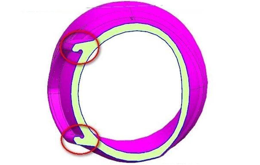
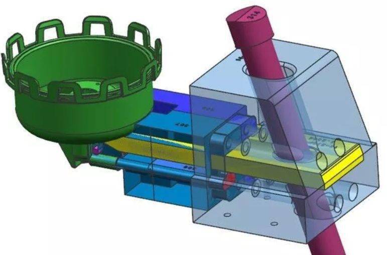
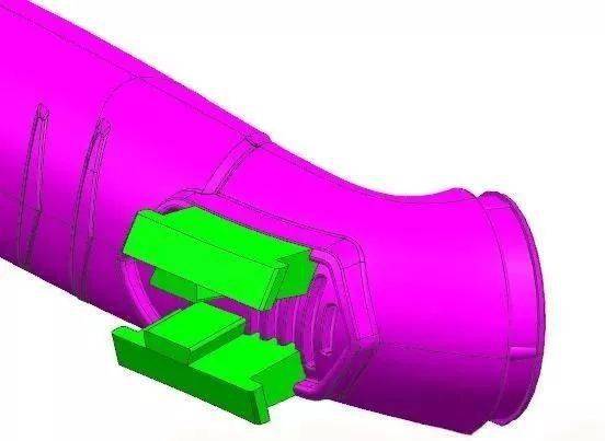
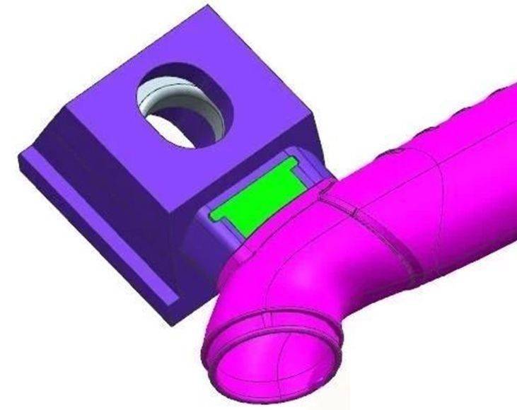
1. Slider design idea: The inner undercut must be detached first, and then the core must be pulled sideways together. As shown in the figure, the small green slider must first be pulled to the middle to get out of the inner buckle.
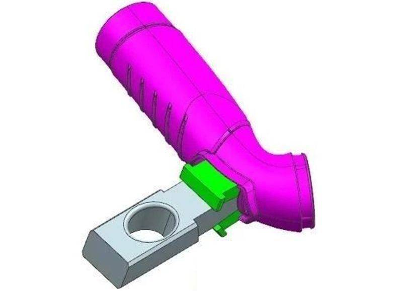
2. The force to drive the small green slider is the gray drive block, designed with a dovetail groove and driven by the inclined guide post, as shown in the figure:
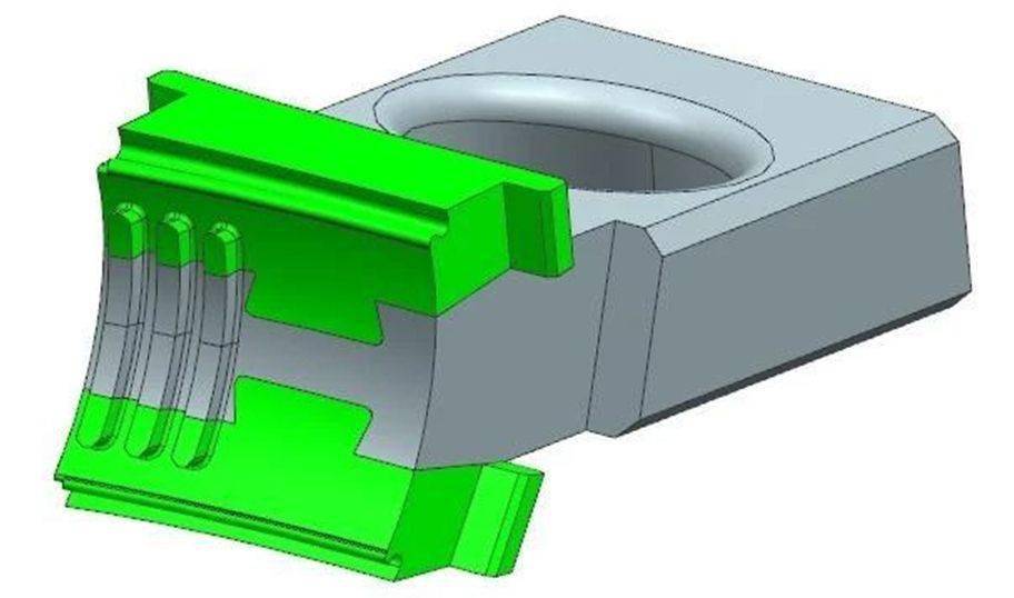
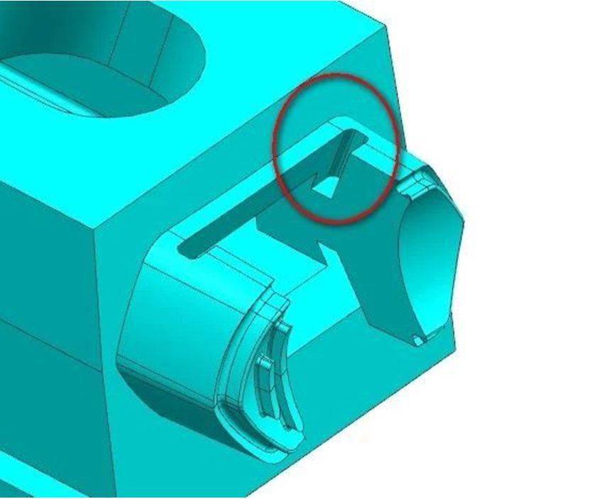
3. Since the small green slider must be pulled out of the buckle first, and the large slider cannot be core pulled first, a delay mechanism must be made. The through hole of the oblique guide post of the large slider is designed as an ellipse, as shown in the figure:
4. The small green slider must be designed with a limit device to allow it to slide in the direction of the trip, as shown in the figure: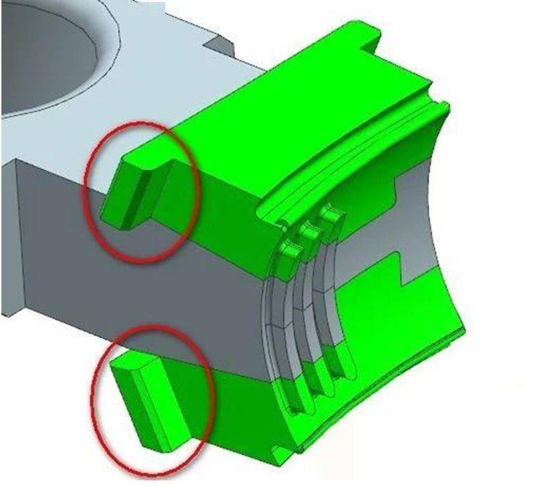
Case 2:
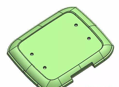
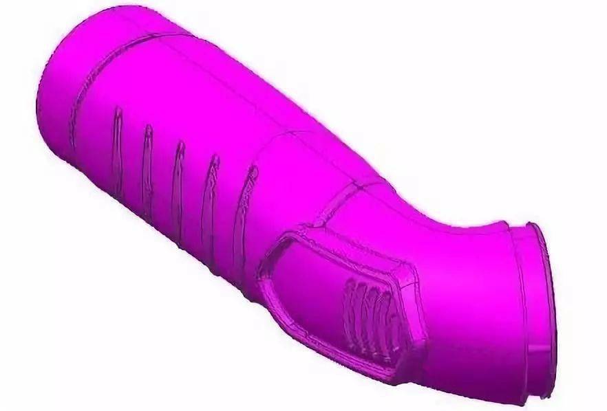
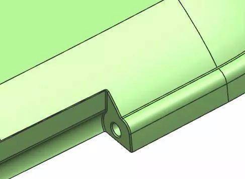
1. This product has two side holes, it is impossible to mold out the ordinary slider, you need to design the slider inside the slider。
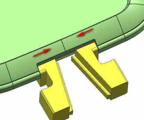
2. First, design two small sliders with dovetail grooves on the inclined surface. The ejection direction of the small sliders is the direction of the red arrow.
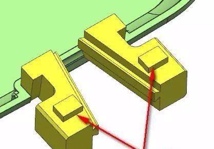
3. When the small sliding block slides, a pipe position is required, and a guide groove is required to be opened in the rear mold core, as shown in the figure:
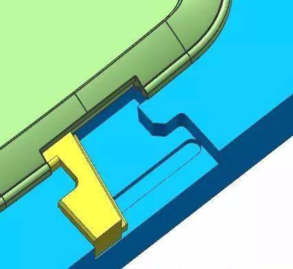
4. Design the insert to drive the small slider and match the dovetail of the small slider, as shown in the figure.
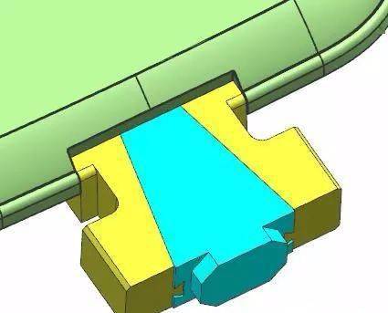
5. The inclined guide post drives the slider to pull the core sideways, and the small slider is driven inward through the dovetail groove to complete the side hole core pulling.
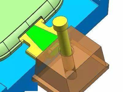
Case Three:
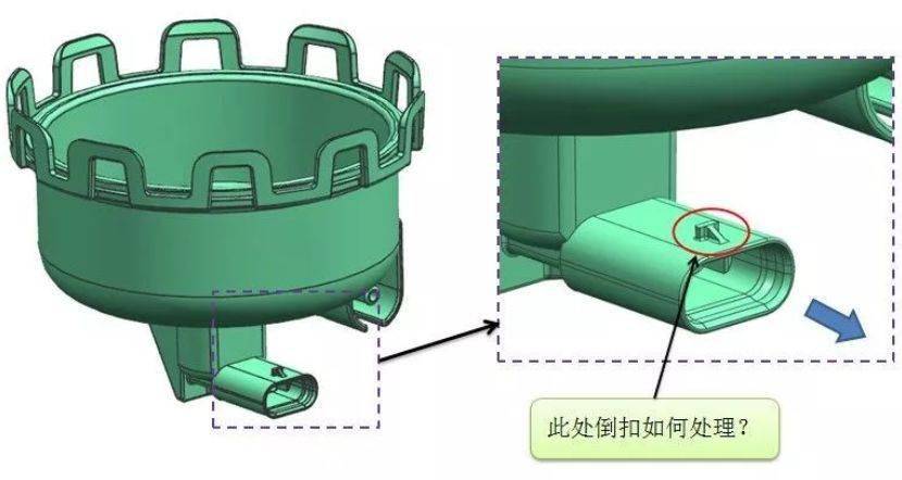
1. Design the slider insert first, and the bone position inside will not be processed temporarily, as shown in the figure.
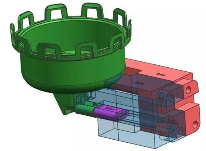
2. Design a small sliding block, using a dovetail groove to drive the small sliding block, the pink square is the positioning block, and the yellow driving block is drawn in the direction of the arrow. Due to the dovetail groove, the small sliding block slides down and is free from the undercut:
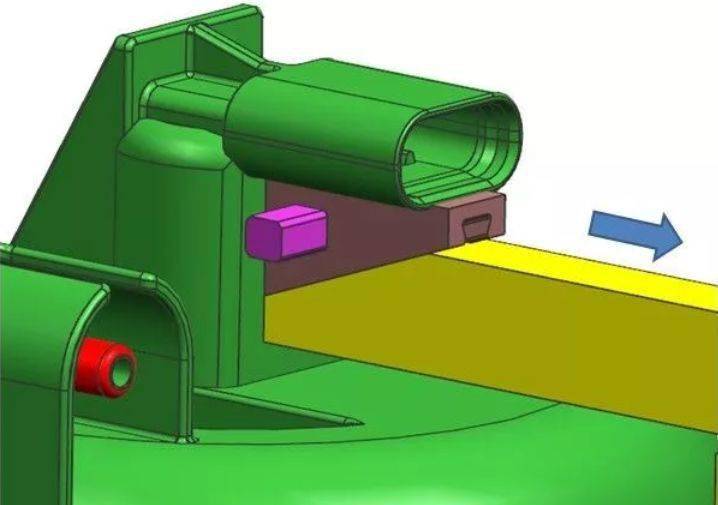
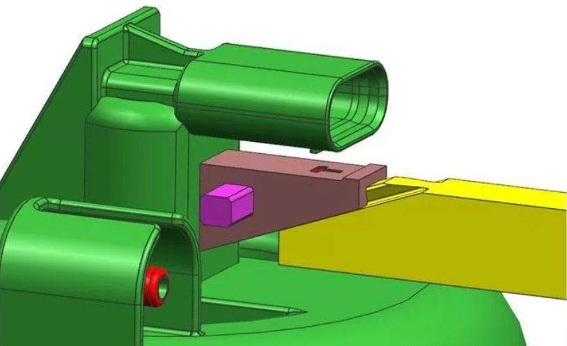
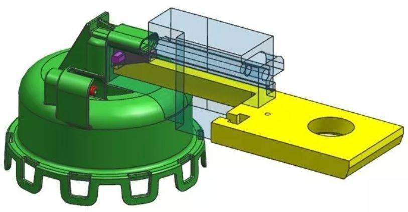
3. Use the inclined guide post to drive the slider, the slider needs to be delayed core pulling, first drive the yellow drive block, drive the small slider to pull the core, wait for it to be released from the undercut, delay the core pulling in place, continue to pull the core, and take off all Undercut.
