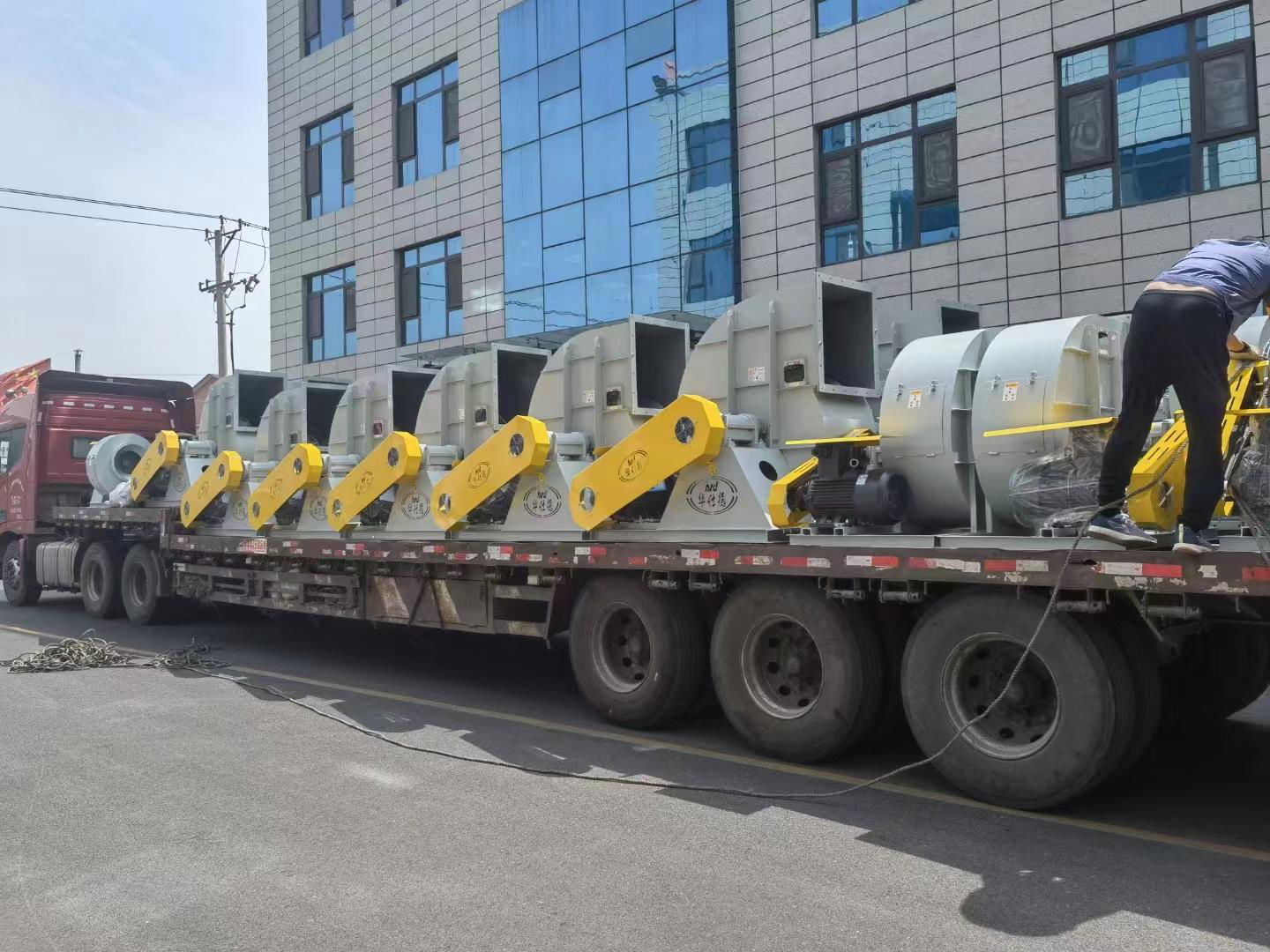
9-12風機的用途及特點
9-12型高壓離心通風機,一般用於鍛冶爐及高壓強制通風,並可廣氾用於輸送物料、輸送空氣及無腐蝕性、不自燃、不含粘性物質之氣體。介質溫度一般不超過250℃(最高不超過300℃),介質中所含的塵土及硬質細顆粒不大於150mg/m3。本系列風機除具有以上特點外,還具有效率高、噪聲低、流量調節範圍大、高效區寬廣、性能曲線平坦等優點。風機"三化"程度高,通用性好,適用範圍廣。
風機的型式
1、 風機製成單吸入,常用機號有№3、3.15、4、4.5、5、5.6、6.3、7.1、8、9、10、11.2、12、12.5、14、16、18、20等,共20多個機號。
2、 風機可製成右旋轉或左旋轉兩種型式,從傳動組部正視風機,如葉輪順時針旋轉稱為順時針旋轉風機即右旋風機,以“右”表示,逆時針旋轉,稱為逆時針旋轉風機即左旋風機,以“左”表示。
3、 風機的出口位置以機殼的出風口角度表示,“順”“逆”均可製成0°、45°、90°、135°、180°、225°、270°共7種角度。
4、 風機的傳動方式有A、B、C、D四種:
A一表示風機軸盤通過鍵槽安裝在電機軸伸上,即電機直插;
B一表示懸臂支承裝置,皮帶傳動,皮帶輪在兩軸承中間;
C一表示懸臂支承裝置,皮帶傳動,但是皮帶輪在軸承外側;
D一表示懸臂支承裝置,用聯軸器聯接驅動。
風機的結構
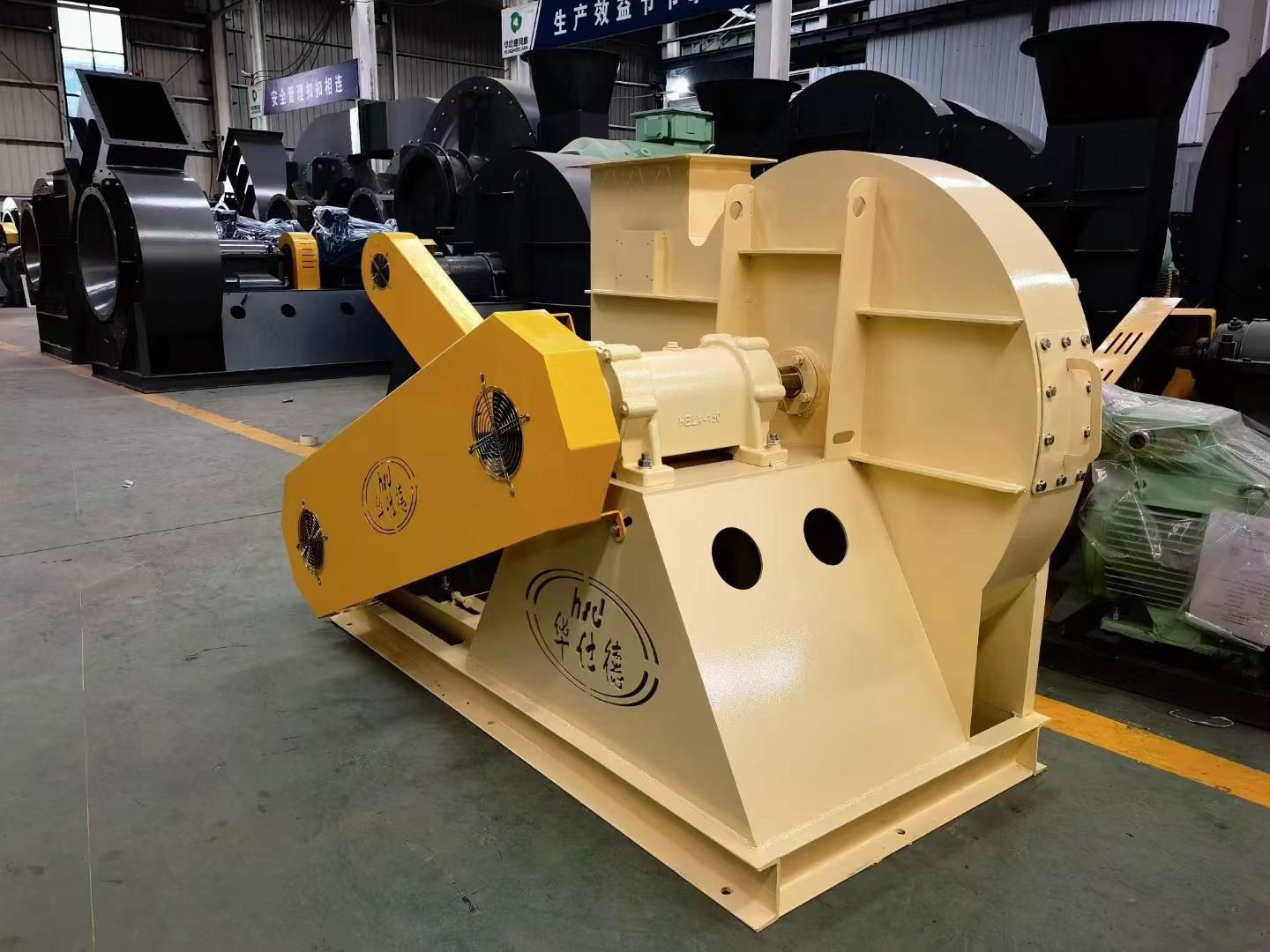
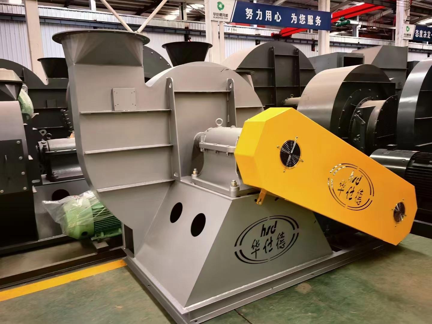
№3~7.1風機主要由機殼、葉輪、進風口、支架等部件組成;№7.1~以上型號風機主要由機殼、葉輪、進風口、傳動組等部件組成。
機殼:由普通鋼板焊接成蝸形殼整體。
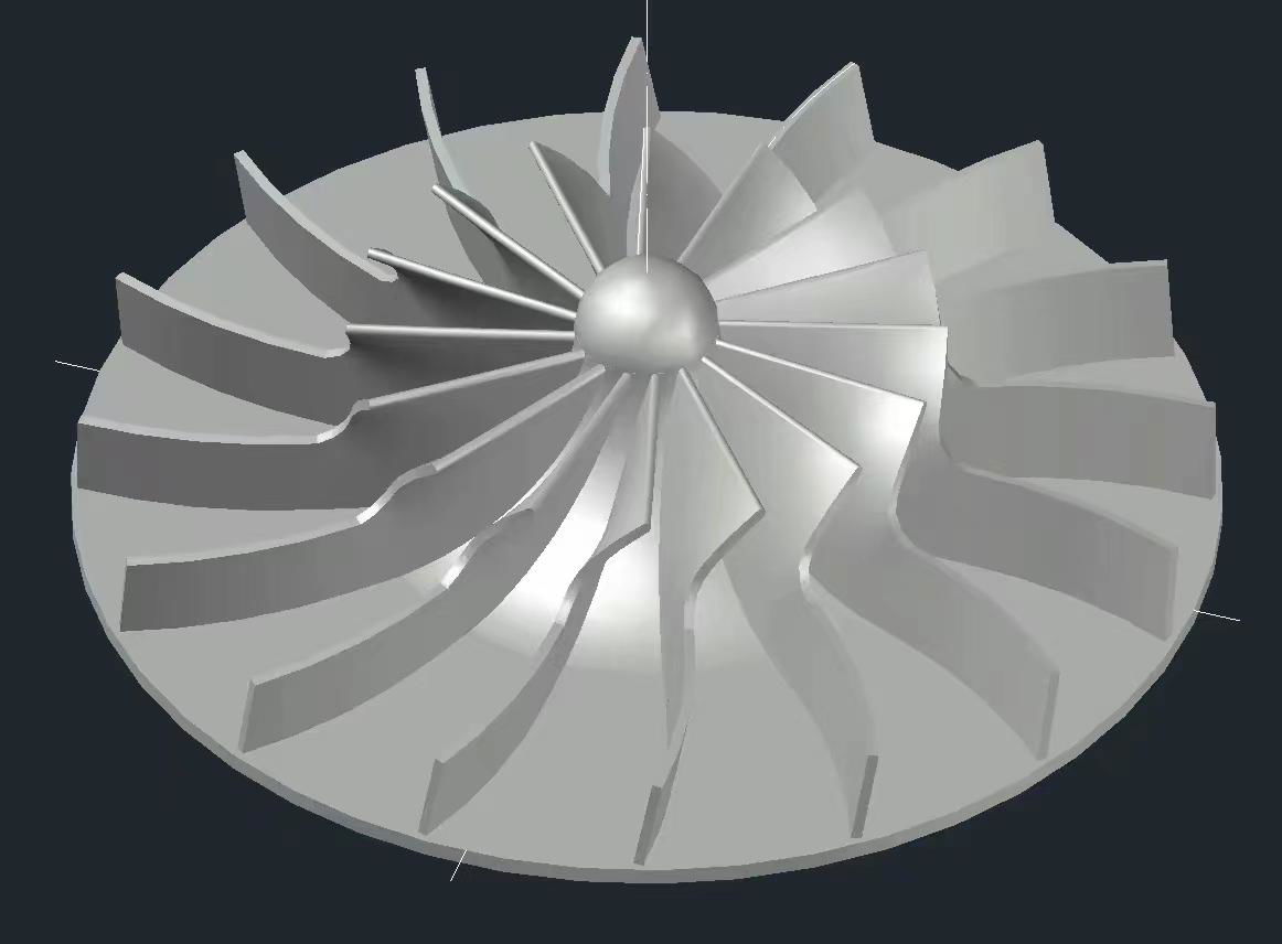
葉輪:風機葉片為20片前向彎曲葉片,均勻相間地焊接于四圓弧型輪蓋與平板型輪盤之間,組成的流道帶有無葉擴壓器,葉輪擴壓器外緣最高圓周速度不超過140m/s,葉輪經靜、動平衡校正和超速運轉實驗,運轉平穩可靠。
進風口:做成收斂式流線型的整體結構,用螺栓固定在前蓋板上。
傳動組:由主軸、軸承箱、聯軸器(皮帶輪)等部件組成,主軸由優質鋼製成,軸承箱為整體結構,採用滾動軸承,滾動軸承用軸承潤滑脂潤滑。
風機的性能與選擇
風機的性能:風機的性能以風機的流量、全壓、主軸轉速,軸功率等參數表示。選擇曲線與性能表中所給出的性能。送風機性能:t=20℃、大氣壓力Pa=101325Pa 、氣體密度ρ=1.2Kg/m³空氣介質計算。(其他設計均按使用參數進行相似換算)
選擇曲線與性能表中性能均指調節葉片為全開0℃時的性能。訂貨時以性能表為準。風機性能試驗全壓值的偏差不超過設計全壓值的5%。
如風機使用條件與上述不符時,性能應按相關公式進行換算。
流量過多或不足時的處理。在使用時,常常發生流量過多或不足的現象,產生這種現象的原因很多,如果是在使用過程中發生流量時大時小的現象,主要是由於管網中的阻力時大時小。如果是在使用過程中,經過較長時間逐漸減少,主要是由於管網堵塞。
在風機新安裝后,進行正式運轉時就發生流量過大或不足現象的原因主要有下列幾點:
1、管網阻力實際值與計算值相差過大。
由一般管網特性方程式:P=Kq²,式中K—阻力係數。
如實際值K小於計算值K時,則流量增大,若實際值K大於計算值K,則流量減小。
2、選擇時未考慮風機本身全壓值編差δP的影響,當風機實際全壓為正偏差時,則流量增大;為負偏差時,則流量減小。
在風機新安裝后開始正式運轉時,或在使用過程中發生流量過大或過小時,可採用下列方法之一消除之;
利用增減風機的轉速調節流量。
利用調換新的壓力較高或低的風機以增減流量。
改變管網阻力係數K以改變流量。
此時可設法改變管網使阻力係數減小以增加流量,也可增加風機轉速和調換壓力較高的風機,但轉速不得大於性能表中最大轉速。
風機的安裝與使用
安裝前:應對風機各部件進行全面檢查,機件是否完整,葉輪與機殼的旋轉方向是否一致,各部聯接是否緊密,葉輪、主軸、軸承等主要機件有無損傷。傳動組是否靈活等。
安裝時:注意檢查機殼,機殼內不應有掉入或遺留的工具或雜物,在一些結合面上為了防止生鏽,減少拆卸困難,應塗上一層潤滑脂或機械油,風機與地基結合面和風機與進出風管道聯接面應調整使之自然吻合,不得強行聯接,更不許將管道重量加在風機各部件上,並注意保証風機的水平位置。
安裝要求:
1、 按圖紙所示的位置與尺寸安裝,為確保高效率,特別要保証進風口與葉輪的軸向和徑向間隙尺寸(出廠前已調整好)。
2、 安裝后試撥傳動組,檢查是否有過緊或與固定部分磨擦現象。
3、 全部安裝完畢,總檢合格后,才能進行風機的試運轉。
4、 為防止電機過載燒燬,在風機啟動時,必須在無載荷(將進風閥門關閉,出風閥門稍開)的情況下進行,如情況良好,逐步開啟閥門,直到達到額定工況為止。在運轉過程中應嚴格控制電流,不得超標。
風機的操作
風機啟動前,應進行下列準備工作。
(1) 將進口閥門關閉,出口閥門稍開。
(2) “點車”查看風機及其系統有無異聲、異振,如有應排除之,如無,點車時間逐漸拉長,直至正常運行。
(3) 風機啟動達到正常轉速時,應在運轉過程中經常檢查軸承溫度是否正常,當軸承溫度沒有特殊要求時,軸承溫升不得超過環境溫度40℃,軸承部分的均方根振動速度值不得大於6.3m/S。如發現風機有劇烈的振動、撞擊、軸承溫升迅速上升等到現象時,則必須緊急停車。
風機的維護
(1) 風機及其系統不許帶病運行。
(2) 風機應由專人保管,專人使用。
(3) 定期清除風機內部積灰,污垢等雜質,並防止生鏽。
(4) 風機的維護必須在停機斷電時進行。
(5) 風機維修、試車時禁止無關人員及行動不便者在場圍觀。
(6) 風機試車時,在風機進出口方向十米之內不許站人。
(7) 風機維修后應清點工具及其它用品,以防遺留在風機及管道內部。
(8) 除每次檢修后應更換潤滑劑外,正常情況下根據實際情況更換潤滑劑。
風機的主要故障及原因
1、 風機劇烈振動
(1) 風機軸與電機軸不同心。
(2) 機殼與葉輪或進風口與葉輪摩擦。
(3) 基礎的剛度不夠或不牢固。
(4) 葉輪鉚釘鬆動或葉輪變形。
(5) 葉輪軸盤孔與軸配合鬆動。
(6) 機殼、軸承座與支架,軸承座與軸承蓋等聯接螺栓鬆動。
(7) 風機口、出風管道安裝不良,產生共振。
(8) 葉片有積灰、污垢、葉片磨損、葉片變形、軸彎曲等原因使轉子不平衡。
2、 軸承溫升過高
(1) 軸承箱劇烈振動;
(2) 潤滑劑質量不良、變質或含有灰塵、砂粒、污垢等雜質或填充量不足;
(3) 軸承箱蓋、座聯接螺栓之緊力過大或過小;
(4) 軸與滾動軸承裝歪斜、前後兩軸承不同心;
(5) 滾動軸承損坏或軸彎曲;
3、 電機電流過大或電機溫升過高
(1) 開車時進、出氣管道閘門未關;
(2) 電機輸入電壓低或電源單相斷電;
(3) 受軸承箱劇烈振動的影響;
(4) 主軸轉速超過額定值。
訂貨需知
訂貨時請註明風機型號、機號、流量、全壓、輸送介質、使用溫度、出口角度及旋轉方向等。
如用戶之需要與本說明書提供性能不符時,請與本廠設計部門聯繫特殊型號的風機。
Purpose and characteristics of the fan
Model 9-12 centrifugal fan is generally used for forging furnace and high pressure forced ventilation, widely used for materiel delivery and suitable to delivery air and gas of non-corrosion, non self-burn and free of viscous material. The temperature of the delivered medium shall normally not exceed 250℃(not exceed 300℃ maximum), the dust contained in the medium and hard-fine particle shall not be bigger than 150mg/m3. This series of fans in addition to the above characteristics,but also has high efficiency, low noise, large flow adjustment range, flat performance curve and so on. Fan three high degree of versatility, good versatility, wide range of application.
Type of fan
1. The fan is made as a single suction and its driving is A type. There are more than 20 types of fan numbers which are 3、3.15、4、4.5、5、5.6、6.3、7.1、8、9、10、11.2、12、12.5、14、16、18、and 20.
2. The fan can be made of 2 types of rotation i.e, right and left. Viewing from one end of the motor, it is called as clock-wise fan if the impeller rotates clock-wise, shown as “right”, On the contrary, it is called as counter-clock-wise fan if the impeller rotates counter-clock-wise, shown as “left”.
3. The outlet position of the fan can be expressed from the outlet angle of the casing. It can be made 7 kinds of angles which are 0°, 45°,90°, 135°,180°,225°, 270°,from both “Right” and “left”.
4. There are 4 driving modes: A,B, C, D:
A—Shaft disc of fan is installed on motor shaft by keyway, i.e. motor directly connecting;
B—Cantilever bearing unit, belt driving, pulley is in the middle of two bearings;
C—Cantilever bearing unit, belt driving, but the pulley is outside the bearing;
D—Cantilever bearing unit, coupling directly driving.
Structure of the fan
№3-7.1 fan mainly consists of impeller, casing and inlet. №7.1- above fan mainly consists of impeller, casing inlet and Driving unit.
Casing: to be welded into a volute with normal steel plate.
Impeller: The fan has 20 forward-curved blades. The maximum circumference speed of impeller diffuser shall not exceed 140m/s. The impeller, after being shaped, shall be balanced statically and dynamicaly and thus it guarantees a smooth operation.
Inlet: to be integrated into a convergent streamlined structure and bolted on the front cover.
Driving unit—it consists of shaft, bearing box, rolling bearing, belt pulley or coupling.
See the attached drawing for installation and overall dimension.
Performance and selection of the fan
Performance of the fan:The performance of the fan is expressed by the parameters of fan flow, full pressure, spindle speed, shaft power and so on. Performance curve and the performance of the performance given in the table. Blower performance: When ordering the performance table shall prevail. Fan performance test total pressure value of 5% of the total pressure deviation is less than design value.
Such as fan using condition does not accord with the above, the performance shall be carried out according to the related formula conversion.
When excessive or insufficient flow of processing. When use, often occur the phenomenon of excessive or insufficient flow, produce a lot of reasons for this phenomenon, if it is in use process flow occurs when small phenomenon, is mainly due to the resistance of pipe network. If it is in use process, after a long time to reduce gradually, mainly due to network congestion.
After the fan is a new installation, a formal operation occurs when the flow phenomenon of excessive or insufficient reason mainly has the following points:
1、The actual value and calculating value difference is too large in the resistance of pipelines.
By the general network characteristic equation: P = Kq, type of K - drag coefficient.
If the actual value K is less than the calculated value K, increases the flow, if the actual value is greater than the calculated value K K, the flow decreases.
2、When the choice is not the fan itself fully considering the influence of the pressure deviation of P, when fan actual total pressure for positive deviation, then the flow; Negative deviation, the flow rate decreases.
Began formal operation after fan is a new installation, or in use process flow is too big or too hours, one of the following methods can be used to eliminate the;
Make use of the fan speed adjusting flow increase or decrease.
Using the new high or low pressure switch to increase or decrease in flow rate of fan.
Change the pipeline resistance coefficient K to change traffic.
At this time to try to change the network reduce drag coefficient to increase traffic, also can increase the fan rotation speed and changing the high pressure fan, but speed shall not be greater than the maximum speed performance table.
Installation and use of fan
9-19 type fan only gives the non-dimensional performance table of №10 sample fan (see table1). The dimensional performance of the fan can be calculated with given non-dimensional performance table.
The dimensional parameter formula is calculated with non-dimensional
parameter.
If it is in non-standard state when operating, the performance of non-standard standard state must be converted to the performance of standard state. And then select fan according to the converted performance. The converting formula is as follows:
Installation and operation of the fan
Before installation: Check all components of the fan to see weather any thing is missed; weather the impeller rotates in the same direction as the casing; weather all components are connected tightly and weather the impeller rotates freely.
During installation: Pay attention to check the casing and any tools or goods should not be dropped and remained inside the casing. The connecting face between the support of the fan and the foundation or between pads and foundation should be tight. Adjusting should be made to joint the fan with foundation surface and to connect the fan with suction, discharge duct naturally. Forced assembling, especially, applying weight of pipes on any components of the fan isimpermissible. Also, attention shall be paid to the horizontality of the fan.
Requirement of installation:
(1) Install the fan according to the position and sizes shown on the drawing. To
insure high efficiency, radial and axial clearances between inlet and impeller must be guaranteed.
(2) After installation, turn, with a little force, the driving rotor to see if it is over
tight or touched with stationary components.
(3) Commission Can only be carried out after the unit is through the final
inspection. In order to prevent the motor being burnt out due to overloading, the fan
can only be started up and tested without loading. If the case is ok, increase the load
step by step until the rated operating condition is reached. Control the current strictly
during operation to prevent it exceeding the rated value.
Operation of the fan:
(1) Before starting-up, the following preparations shall be made:
a) Close the valve of suction pipe and open a little the valve on discharge pipe.
b) Check the rotating and non –rotating parts to prevent colliding and friction.
(2) After the fan is started-up and the normal speed is reached, check the bearing temperature is normal or not during the operation. If there is no special requirement for bearing temperature, the temperature rise of the bearing shall not exceed 40℃ of surrounding temperature. The value of even root vibration speed of the bearing shall comply with the following rules: rigid support(support is fixed on the foundation) Vrms≤4.6mm/s; flexible support(be set onfoundation or floor through absorber) Vrms≤7.1mm/s. In case that severe vibration, colliding, quick rise of bearing temperature and other abnormal phenomena are found, stop the fan immediately.
Maintenance of the fan
1) Cautions in fan maintenance:
① The fan can only be put into operation in normal condition.
② When the fan is started-up after inspection, attention should be paid to see
weather each component is ok or not.
③ Check periodically the dust and contamination inside the fan to prevent rust.
④ Maintenance can be carried out during shut down of fan to assure operators
safety
2) Cautions in normal operation of the fan
① During the star-up, shut-down or operation of the fan, if some abnormal thing
happens, inspections shall be carried out immediately; if it is small failure, the reason shall be checked out and eliminated, if it is a big failure, the fan shall be stopped and inspection and maintenance shall be made immediately.
② Replace lubricant grease of motor bearing according to the real condition.
The main failure and reason of the fan
1) severe vibration of the fan
① friction between casing (or suction unit)and impeller.
② Foundation is not rigid enough or firm enough.
③ loosing of rivets in impeller or deformation of impeller.
④ Loose match of shaft with impeller disc
⑤ Loose of connecting bolts between casing and support, and between motor and
support.
⑥ The installation of inlet and outlet ducts is improper which causes the casing
deformation and resonance.
⑦ Rotor unbalance caused by dust, contamination on blades, wear of blades,
deformation of impeller and bending of shaft.
2) High rise of bearing temperature
①severe vibration
② lubricant is poor in quality, deteriorated, mixed with dust, sand, contamination
and etc, or insufficient in quantity.
③Wornout of rolling bearing
3) Overcurrent and high temperature rise in motor.
① The valves on inlet and outlet pipes are not closed completely when starting-up.
② Input voltage is low or a single phase of power supply is cot out.
③ Influence caused by severe vibration
④ The speed of main shaft is bigger than the rated value.
Supply scope of fan unit
One fan, one driving motor and 4 sets of foundation bolts
Purchase information
1)when purchasing, indicate the size, speed, flow, pressure, discharge angle and rotating direction of the fan, and the model, power, and speed of the motor.
2)Also, indication shall be made clearly when ordering, if you need inlet filter, silencer, inlet and outlet soft connection, vibration absorbing platform and vibration absorber.
