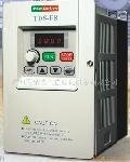
| Control Characteristics |
Operation Mode |
LED Operator or LCD Operator |
| Control Mode |
Sine PWM |
| Frequency Control Range |
0.1Hz~400Hz |
| Frequency Accuracy(varied with temperature) |
Digital Command:±0.01%(-10 ~ +40℃),
Analog Command:±0.1% (25℃ ±10℃) |
| |
| Frequency Command Resolution |
Digital Command:0.01Hz,
Analog Command:0.06Hz/60Hz |
| |
| Frequency Output Resolution |
0.01Hz |
| |
| Overload Resistibility |
150% Rated Current for 1 Minute(CT) ; 120%Rated Current for 1Minute(VT) |
| Frequency Setting Signal |
DC 0 ~ +10V / 4 ~ 20mA |
| Acc./Dec. Time |
0.0~6000.0 sec (Accel/Decel Time Can be Set Independent) |
| Voltage-Frequency Characteristics |
V/F Curve Can be Set Through Paramenter Setting(16Types) |
| |
| Regeneration Torque |
100%,2%ED,5 sec |
| Main Control Function |
Auto Torque Boost, Slip Compensation, Restart After Momentary Power Loss, Energy-Saving, |
| PID Control, RS-485 Communication, Simple PLC Function, Sensorless Vector Control |
| Extra Function |
Up/Down Operation, 4 Different Sets of Fault Status Record (Including Latest One), |
| |
cumulative Power On & Operation Hour Memory, Energy Savings Function, |
| |
MODBUS Communication, Multiple-Pulse Output Ports, etc. |
| Protection Function |
Stall Prevention |
During Acceleration/Decelearation and constant speed opearation |
| Current Level can be Selected During Acceleration and Constant Speed Operation |
| During Deceleration, Stall Prevention can be Enabled or Disabled) |
| Instantaneous Overcurrent (OC) |
Stopped if above 200% Rated Current |
|
|
|
|
|
|
|
| Inverter overloads Protection(OL2) |
Stopped if above 150% Rated Current for 1 Minute |
|
|
|
|
|
|
|
|
| Motor Overload (OL1) |
Electronic Overload Curve Protection |
|
|
|
|
|
|
|
|
| Over voltage(OV) |
Motor Coasts to Stop if VDC > 410V (230V) or VDC > 820V (460V) |
|
|
|
|
|
|
|
|
| Low voltage(UV) |
Motor Coasts to Stop if VDC < 200V (230V) or VDC < 400V (460V) |
|
|
|
|
|
|
|
|
| Momentary Power Loss Ride-Through time |
Motor Coasts to Stop after Momentary Power Loss Lasting > 15ms |
|
|
|
|
|
|
|
|
| Overheat (OH) |
Protection by Thermistor |
|
|
|
|
|
|
|
|
| Grounding Protection (GF) |
Protection by the DC Current Sensor |
|
|
|
|
|
|
|
|
| Charge Indication |
Light when the DC Bus Voltage ≧50V |


