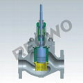
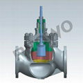
| Model: | 10M |
|---|---|
| Brand: | REOWO |
| Origin: | Made In China |
| Category: | Industrial Supplies / Machine Hardware / Valves |
| Label: | control valve , valve , unbalanced trim valv |
| Price: |
US $50
/ pc
|
| Min. Order: | 1 pc |
Product Description
|
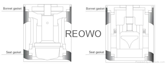
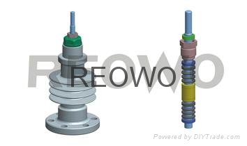
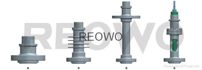
The 100 series control valve design features Innovative packing structure design The top guided structure design Detachable structure design Standard modular design Readingtips For detailed product information, product animation, please click "contact us", then visit the company's website, Download and reading Or contact us directly |

Outline
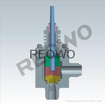
The 10M Series unbalanced labyrinth control valve adopts the labyrinth cage and unbalanced trim design. The labyrinth sleeve is composed of cylindrical discs with many coaxially distributed labyrinths. According to different technological parameters of the media, different labyrinth specifications and piling layers are designed to form the cage and the cage divides the whole flow channel into several tiny circuitous or step flow channels, forcing the fluids to continuously change the flow direction and flowing area and gradually reducing t he pressure of fluids, so as to prevent the occurrence of flash evaporation and cavitation and prolong the service life of the trim. The unbalanced single seat is adopted. The trim is suitable for service conditions under which blocked flow will easily be produced and cavitation will be caused. The unbalanced trim is suitable for applications of small sizes and high temperature.
Parameters of control valves
|
DN |
20~450mm |
|
PN |
Class150~2500 |
|
Applicable temperature range |
-196℃~570℃ |
|
Trim features |
sleeve guided unbalanced trim structure, labyrinth disc cage combination |
|
Body type |
straight-through type, angle type |
|
Bonnet type |
standard type, heat dissipation type, cryogenic type |
|
Flow characteristic |
equal percentage, linear, quick open |
|
Shut-off class |
ASME B16.104 V (standard metal seat) |
|
ASME B16.104 VI (shut-off soft seat) |
|
|
Pipe connection type |
flange type, butt welding type |
|
Actuator type |
pneumatic diaphragm actuator |
|
pneumatic piston actuator |
|
|
Electric actuator |
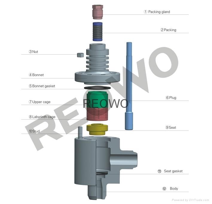
Exploded view of 10M Series (unbalanced trim)

Speed control principle of labyrinth control valve
The valve that is damaged by cavitation, flash evaporation, vibration and noise produced by the media that passes through the valve at a high flow velocity is the main cause that leads to failure of control in the system. Even if the valve is not damaged, bad process control caused by too high noise and severe vibration will lower product performance and influence the running capacity of the equipment. Based on the principle of fluid mechanics,the labyrinth control valve adopts speed control principle and technology and makes use of multi-stage pressure drop to eliminate cavitation, flash evaporation, vibration, noise, etc .,providing overall system control solutions form any different application fields.Under severe service conditions, bad performance of valves is caused by too high flow velocity. The maximum flow velocity of the fluids in the valve always
occurs at the throttling face(figure1) which is at the downstream side of the restriction orifice of the plug .Even if materials of relatively high hardness are used in the valve to control the damage caused by cavitation ,only a small amount of faults in the valve caused by too high flow velocity of the media can be eliminated. The flow velocity of media in all valves must be controlled so as to maintain the performance and reliability of the valves.

The labyrinth flow channel can realize control of flow velocity
The labyrinth control valve can prevent the plug from producing high flow velocity and ensure the final control effect: The medium pressure and flow velocity can be effectively controlled during the whole travel of the valve .The labyrinth cage scatters the fluids into several split flow to reduce the flow velocity as much as possible (figure2). Each fluid channel is composed of specific quantities of right-angled bends that form the labyrinth flow channels(figure3). During the process, each bend will reduce the flow velocity of the flowing media to a certain extent .The bend number N is the number that is required for scattering the maximum differential pressure in the plug (figure4). See the following formulas:

Cause of cavitation
When the fluid pressure is reduced to The saturated vapor pressure or lower, flash evaporation or bubbles will occur. In most control valves(figure5), the inlet pressure is P1, velocityisV1. When the fluid passes through the plug necking area, the velocity is increased to Vvc . According to the principle of conservation of energy, the fluid pressure suddenly drops to Pvc .When Pvc is equal to or less than the liquid saturated vapor pressure Pv, the liquid will be gasified and bubbles will be produced, so that flash evaporation occurs.
After the fluid passes through the plug, the pressure starts to be restored and the kinetic energy is transferred into potential energy again. When the pressure is restored to the downstream pressure, which is expressed as P2 and the velocity is V2. When the restored pressure exceeds the saturated vapor pressure Pv, the bubbles formed will be broken and cavitation will occur. This kind of energy release will increase the partial stress to be above 200000PSI (1400MPa) and the stress will rapidly destroy the solid plug.
Solution to cavitation
The labyrinth control valve can effectively eliminate the damage caused by failure of control of
fluid velocity. First, the fluids are scattered into many small flow channels. Thus, even the bubbles are formed ,their volume is very small and the energy is not sufficient to produce stress that can damage materials. Secondly, the flow velocity is maintained at the lowest level .Thus ,the partial pressure will not be reduced to be lower than the fluid vaporizing pressure. Therefore, cavitation will not occur.
The damage caused by cavitation is a typical signal that indicates failure of control of flow velocity .As is mentioned above, the adoption of materials of high hardness, insulating sleeve or downward orifice will only eliminate as mall amount of faults in the valve caused by cavitation. The high flow velocity will cause cavitation and damage the plug ,and the solution to cavitation is to adopt the labyrinth cage as shown in figure 6. According to the fluid evaporation pressure ,the flow velocity can be achieved through the following formulas:

Design of labyrinth disc of labyrinth control valve
Determine the bend number N and select the number to ensure the flow velocity when the fluid flows out of the flow passage. Each cage forms multi-layer labyrinth groups (figure7) by adopting special technology .The labyrinth discs are processed into several flow channels similar to the labyrinth through special forming technology (figure8). According to different service conditions, after precise calculationand in combination with CFD flow filedanalysis (figure9), each flow channel is designed with a series of right-angled bends of specific quantity to provide resistance for media and reduce the velocity stably. The technology can fully control the velocity of media in all channels of labyrinth discs, so that the media can flow at the controllable velocity within the whole range.
To achieve the flow characteristic required by the system, a labyrinth group shall be composed of 3kindsof labyrinth discs .To meet the requirements of high differential pressure and small flow, the discs at the bottom shall have few flow channels and many bends. The middle labyrinth discs shall have medium flow channels .To meet the requirements of low differential pressure and large flow, the discs at the top shall have many flow channels and few bends. The resistance, quantity and area of all flow channels in the labyrinth control valve can be customized according to the specific applications so as to control flow velocity, eliminate cavitation ,flash evaporation, vibration, noise and etc. that occur during the use of fluids.

Selection of flow direction of labyrinth control valve
For liquid media, the flow direction is side-in and bottom-out. For gas and steam media, the flow
direction is bottom-in and side-out. This is because that the liquid is an incompressible fluid. By
adopting side-in and bottom-out, the high speed liquids at the exits of all flow channels of labyrinth discs will carryout mutual collision on the central axis of the labyrinth sleeve, counteract their energy and form buffer cushion, so as to further lower flow velocity and reduce the erosion of the valve and trim by high speed liquids. The high differential pressure gas and steam are compressible fluids .After pressure drop by the labyrinth discs, the volume expands sharply. This requires that the flow cross-sectional area at the exit should be higher than that at the inlet. Therefore, the flow direction shall be bottom-in and side-out .Otherwise, the pressure drop effect will be influenced.
Member Information
| Zhejiang Jinfeng Automatic Meter Co.,Ltd. | |
|---|---|
| Country/Region: | Shang Hai - China |
| Business Nature: | Manufacturer |
| Phone: | 52805955 |
| Contact: | Zoe (Sales Manager) |
| Last Online: | 09 Oct, 2014 |
Related Products of this Company
-
30D03Y/30D03R self-operated differential
US $50
-
70D Series three-eccentric butterfly
US $50
-
10PF Series control valve
US $50
-
Pneumatic actuator
US $50
-
50P Series eccentric rotary valve
US $50
-
30D02Y/R self-operated (before-valve)
US $50
-
10S Series control valve
US $50
-
70ESeries high-performance Butterfly
US $50
-
10M Series control valve
US $50
-
RW series actuator
US $50
