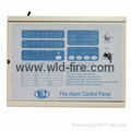
| Model: | 8200-1 -2 -4 |
|---|---|
| Brand: | WLD |
| Origin: | Made In China |
| Category: | Security & Protection / Alarm |
| Label: | FIRE ALARM PANEL , PANEL , ALARM |
| Price: |
¥48.8
/ pc
|
| Min. Order: | 100 pc |
Product Description
INSTALLATION
Remove the locking screw which holds the front panel door closed. Mount the panel as close as possible to the mains and zone cabling, and connect the supply accordingly. Connect the batteries as per the diagram below, and check to see that panel is slient, with only the mains healthy lamp being illuminated.(the EOL devices should still be in place at this stage).
***Should you encounter any problems at this stage, DO NOT***
*** PROCEED, but contact your supplier for assistance***
Any problems which the panel highlights at this stage will be due to inappropriate field wiring. MAKE SURE IT IS CHECKED FIRST.
Disconnect all sources of supply (including batteries).and proceed to terminate one zone to the panel. Remove the EOL device from the panel block. and fit to the last detector on the field wiring(across -ve out and +ve on the detector base). Connect the mains and batteries, and ensure the panel is silent as before. Should everything be healthy, repeat this procedure for each zonal circuit until all circuits are connected.
Any problems highlighted at this stage will be due to field wiring/devices connected to each zone. Re-check all cabling and devices if necessary.
BATTERY TERMINATIONS

RED
BLACK

Size:300×200×90mm Fixed Size:180mm
BASIC OPERATION
NORMAL OPERATING MODE
This is the default condition for the system. this mode is indicated by the green LED AC ON being illuminated while all other LED’s are extinguished. In this mode, the system will monitor and react to all alarm and fault inputs. Whenever maintenance for fault finding has been completed, the system MUST be returned to this mode.
ALARM MODE.
This mode is activated by the receipt of the following:
- A smoke detector is activated
- A heat detector is activated
- A manual call point is activated
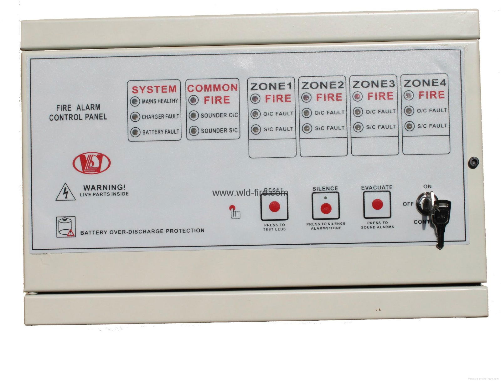
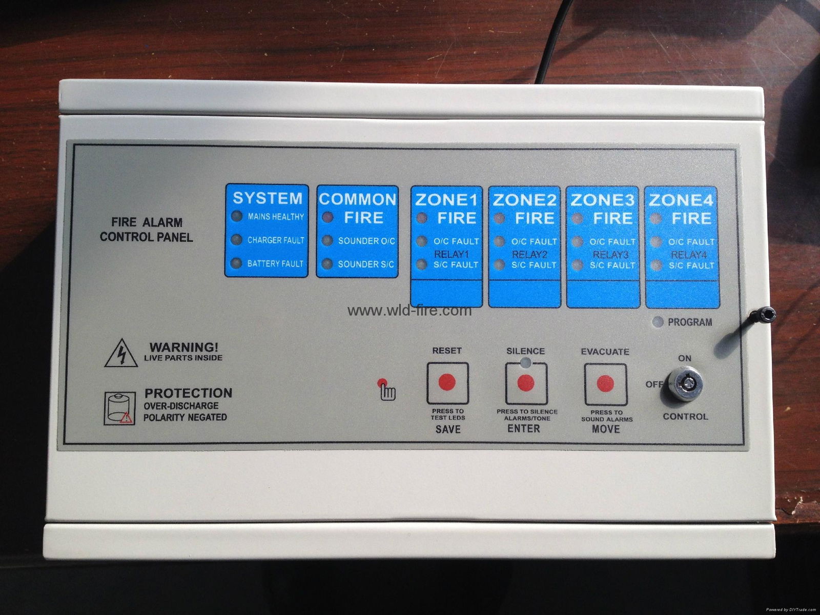
The sounders will operate and the internal Buzzer will sound. The common Alarm LED will illuminate, and the first LED on the zone display (FIRE) will operate.
TO SILENCE ALARM
- Turn the control key to the ON position
- Press the alarm silence(This mutes external sounders and internal buzzer, green LED is illuminated)
- To Restart the sounders, Press EVACUATE.
- To Cancel the fire alarm condition, press RESET.
|
NOTE: The system can only be reset after the MUTE switch has been activated. |
If the panel receives a new alarm during the silence, then the sounders will start operation again. If after RESET the zones are still in an alarm condition then the fire LED’s will not be extinguished, and the sounders will operate.
FAULT MODE
The panel buzzer will sound if any of the following occur:
A Detector fault
B Zone wiring fault
C AC mains failure
D Battery fault or disconnected
E Alarm output wiring fault
The fault LED that will be illuminated will depend on the fault described above.
EVACUATE (ALARM RESOUND)
The EVACUATE switch can be used to activate the alarm in the event of an emergency. It can also be used to re-sound an alarm after the alarm has been silenced.
ZONE AND DISPLAY
Each detection zone is represented by three LED’s, one Red and Two Amber
|
RED |
AMBER O/C |
AMBER S/C |
|
When red LED is illuminated, it indicates an alarm in that zone. |
Indicates an open circuit fault in the field wiring of that zone. |
Indicates a short circuit fault in the field wiring of that zone |
LED TEST
This is provided to check that all fire (red LED’s) are functioniing, and that the illuminated LED’s are providing the correct information.
To activate this feature:
- Press and hold the LED test button is the ON position
- Panel will illuminate all fire Led’s. The internal Buzzer will sound.
|
NOTE:
|
FIELD EQUIPMENT TERMINATIONS
2wire/Normal Mode

2 Wire/Remote Led Indicator
GENERAL SPECIFICATIONS
|
ELECTRICAL |
|
Main Supply………………………….220v AC 50/60 Hz+10% Battery Voltage-----------------------------24V DC Charging Voltage Protection--------------- Resettable Fuse Battery over discharge Protection----------------19V DC Sounder Output------------------------------24V Nominal EOL 300K resistor Auxiliary Contacts--------------------------30DC 1A max. NC/NO. Mains Supply Protection---------------------Glass Fuse Sounder Protection---------------------------- Resettable Fuse Reverse Battery Protection--------------------Charger Resettable fuse Zone EOL----------------------------------------3K6 Resistor |
ZONAL CIRCUITS
Each zone is monitored for an open and short Circuit fault protection. These are given by separate indications on the front panel. Monitoring is achieved with a 3K6 EOL resistor which is supplied fitted. A maximum of 50 detectors per zone is permissible(10mA max.),and any number of call points.
FUSE SPECIFICATION
|
Zone 1 to Zone 4 Control Panel |
Mains Fuse |
1.0A(5X20mm) |
|
Battery Fuse |
300mA |
|
|
Sounder1 Fuse |
500mA |
|
|
Sounder2 Fuse |
500mA |
|
|
Charging Voltage Fuse |
300mA |
SOUNDER CIRCUIT
Two Sounder circuits are provided, each being fuse protected (500mA) and monitored for open and short circuit fault condition via a 300K end of line resistor,supplied fitted. The sounder outputs are effected by any zonal alarm or the Evacuate button on the panel front. Sounder silencing is achieved by pressing the Silence button。The maximum loading on any sounder circuit must not exceed 500mA.
BATTERY STANDBY
|
PANEL |
SUPPLY SIZE |
FOR GUIDANCE ONLY. Battery required for standby times. All alarm times are 1/2 hour |
|||
|
CONDITIONS |
|
|
|||
|
Alm load |
Det.Load |
24+1/2 |
48+1/2 |
||
|
1-4 Zone |
1.2A |
0.3A |
1mA/Zone |
1.2Ah |
1.2Ah |
Charger Short Circuit Protection & Batteries Protection
With intelligent charger, that senses if too much current is being drawn (for instance in the case of totally discharged batteries, or the charger leads being shorted together). In such an event, the NW8200L zone panel will turn off the power to its charger circuit.
The panel also turns off the charger when the batteries are disconnected.
The panel also turns off the batteries when the batteries volt is less than 19V.
In the absence of the main power,The panel can be work by the internal Bat.start key
|
WARNINGS The battery set needs to be replaced at intervals not exceeding 5 years, depending on their usage and general condition. If in doubt, replace after 4 years in services. Upon fitting a new set of batteries, the system must be allowed to charge the batteries for at least 100 hours before they can be considered to be fully charged and therefore capable of supplying adequate back-up in the even of period, but not necessarily able to meet the regulatory specifications. When fitting the battery set to the inside of the panel, they should be secured under the bracket provided to avoid any long term movement. |
CONTROL PANEL TERMININATIONS
1. Sounders, Zones

2、Alarm AUX/Fault AUX

3、RELAY-OUTPUT FOR BELL(SOUNDER)

4、NOTE(Default):

Member Information
| Ningbo Wan Lida electronic technology co., LTD | |
|---|---|
| Country/Region: | Zhe Jiang - China |
| Business Nature: | Manufacturer |
| Phone: | 13336671716 |
| Contact: | Willy wang' (Manager) |
| Last Online: | 28 Jul, 2015 |
Related Products of this Company
-
COVENCIONAL SMOKE DETECTOR
US $3.7
-
CONVENTIONAL FIRE ALARM PANEL
-
CONVENCIONAL HEAT DETECTOR
US $3.6
-
smoke detector + escape light+color
US $3.7
-
CONVENTIONAL FIRE ALARM PANEL
US $93.3
-
COVENCIONAL SMOKE DETECTOR
US $3.7
-
CONVENCIONAL HEAT DETECTOR
-
CONVENCIONAL HEAT DETECTOR
US $3.6
