| Model: | SNV-308 & 309 |
|---|---|
| Brand: | SNOVA |
| Origin: | Made In China |
| Category: | Electronics & Electricity / Power Supply & Distribution / Power Distribution Cabinet |
| Label: | Overhead line , Fault Indicator , Earthfault indicator |
| Price: |
US $1
/ sets
|
| Min. Order: | 10 sets |
Product Description
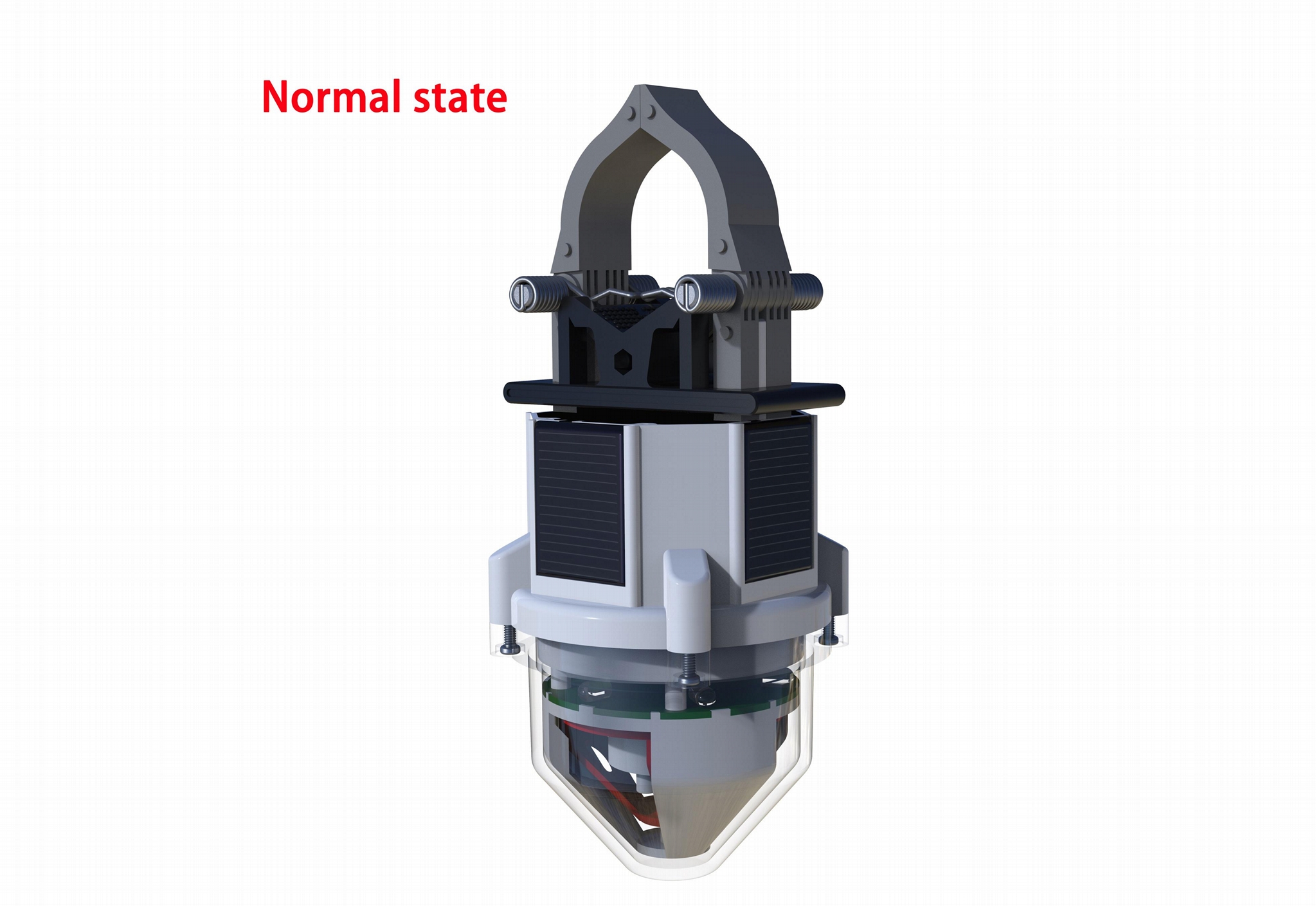
SNV-308&309 Overhead line short-circuit and ground fault indicator
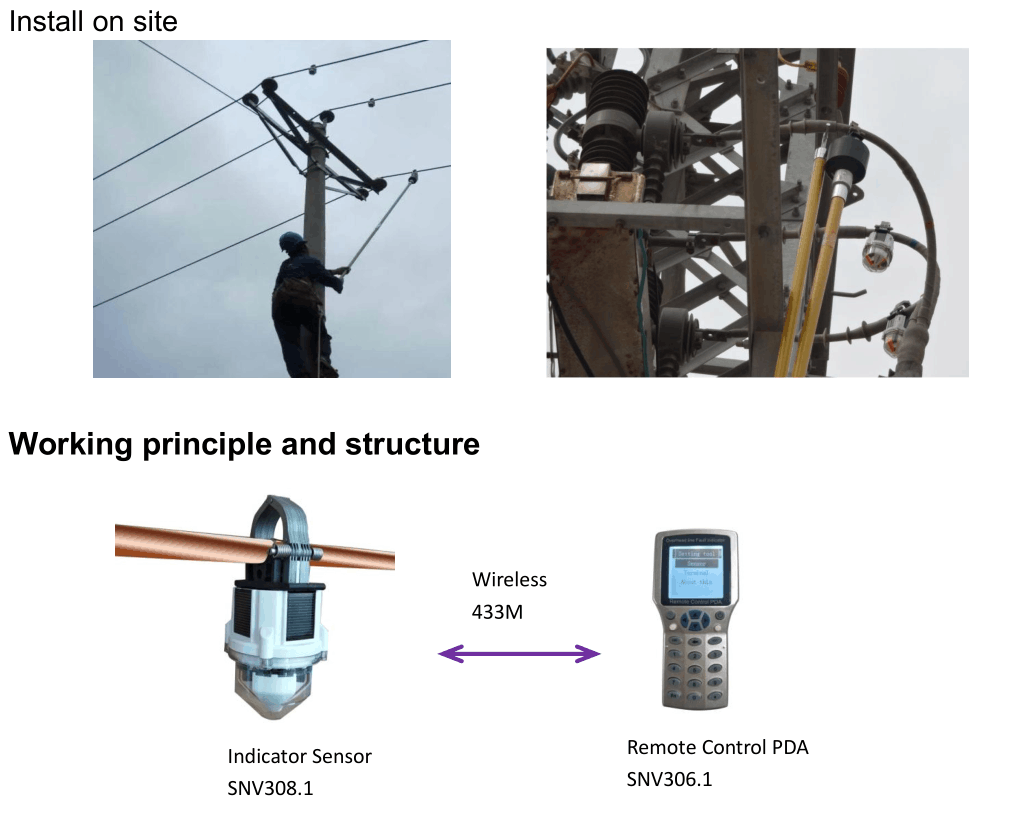
SNV-308 is suitable for overhead line 35KV and below a four remote function grounding and short-circuit fault indicator. APT-308 through real-time measurement and according to the current cable current waveform changes to determine the short-circuit fault on the power lines and grounding fault, and the fault state, real time current (fault current), battery voltage, temperature, electric field of cable and otherinformation uploaded to the remote server, which provides reliable data for the various types of fault diagnosis and location overhead line. SNV- 308 by handheld PDA in the process of using (APT- 307) or communication terminal (SNV- 309) for its flexible configuration to meet the needs of different environment monitoring overhead.
1.Summarize
1.1, Intelligent overhead line fault indicator
It can detect the short-circuit fault, ground fault and measure the line current operating condition accurately. It can communicate two-way real-time with the communication terminal through the wireless. So that it can report the fault status and line operating condition to the communication terminal real-timely. Also, it can receive the test signal, configuration parameter and upgrade programme realtimely from the communication terminal.
1.2. Overhead type data collecting communication terminal
It is used for two-way real-time connection between the wireless remote real-time condition monitoring system and the intelligent overhead line fault indicator. It can report the monitor result to the system, such as fault status and line operation status. At the same time, it can receive the order from the system.
1.3. Wireless remote real-time condition monitoring system
It can collect the fault status and line operation condition from the communication terminal. It can also display monitoring results, alarm, storage and printing. It can also control the parameters of intelligent overhead line fault indicator and its upgrade program
2.Features
|
Self-sustain |
Short-circuit fault detection |
|
The indicator is made with new material and special circuit designed. When the wire load current is greater than 3A, it begins to get the power from the wire. When the wire load current is greater than 30A, it can work normally without the lithium battery totally. |
We use quick break over-current two-stage current or adaptive load current flow mutation current protection principle, and line running status detection, it can effectively inhibit the closing and reclosing inrush current and feedback to send electrical misoperation (the parameters can be set on-line so that the detection can be more sensitive and reliable). |
|
Ground fault detection |
Indication |
|
It can monitor the mutational increment of the grounding current(the parameters can be set on-line so that the detection can be more sensitive and reliable). |
The indication is done by three flashing LEDs for a clear visibility and three red display areas work by motor for a clear daytime visibility. Single-flashing means ground fault indication; double-flashing means short-circuit fault indication. |
|
Reset mode |
Current and voltage measurement |
|
1,1~48h timing reset(can be set on-line, default 24h) 2,Intelligent reset(auto-reset after finish the emergency repair and restoring power transmission)or local/remote control reset via wireless. |
Real-time monitoring of line load current, wire-to-ground voltage induction, instead of using current transformers and live displays. |
|
Live mounted and removal |
Antirust design |
|
The indicator can be mounted under live conditions with the help of an adapter and a hot stick. |
The tension discs are made of high quality nylon material. The groove springs are made of stainless steel so that they won’t melt with the wire. The thread jamming structure parts are made of stainless steel and with antirust design. |
|
Anti refuse operation design |
Anti misoperation design |
|
We adopt large cross-section design of magnetic circuit, it has good permeability performance, accuracy measurement and high sensitivity. They can be very sensitive no matter in the rural power line small load current or small mutations conditions or in the city network line two phase short circuit or slow flow conditions. |
It has anti misoperation design, when the inrush current occurs after the non-loading line is switched on and anti misoperation of non fault branch when it’s on.
|
|
Communication mode |
|
|
Embedded short-range two-way wireless communication frequencyRF modules, the GPRS data can communicate via data collection terminal or wireless repeater. |
|
3. Technical parameters
|
Battery |
6.5Ah/3.6V one long-life lithium battery |
|
Electric power |
50uA~20mA/3.6V(Corresponds to a load current 3A~600A) |
|
Static average power consumption |
≤40uA/3.6V (RF in parameter and command receiving waiting state) |
|
Dynamic average power consumption |
≤50uA / 3.6V (RF transmit data once every five minutes); ≤60uA / 3.6V (RF transmit data once per minute) |
|
Available wire diameter |
8~40mm(Insulated wire, bare wire) |
|
Available load current |
0~600A(Default),0~100A,0~2000A,0~4000A |
|
Available voltage level |
≤35KV(can be set according to the customer) |
|
Quick-break over current Delay |
0~9.99S, Stepping by 0.01s (can be set via local wireless and GPRS on-line remote control) |
|
Quick-break, over current settings |
0~700A or 0~4000A (Phase sequence), 0~70A (Zero sequence), Stepping by 1A(can be set via local wireless and GPRS on-line remote control) |
|
Maximum earth impedance |
500Ω |
|
Maximum short circuit current |
40KA |
|
Communication frequency (RF) |
Center frequency: 434MHz, 64 channels automatic frequencyadjustment, two-way communication |
|
Communication distance (RF) |
30~100m(10dbm,open area);100~300m(20dbm,open area) |
|
Voltage Linearity |
Better than ±5% |
|
Current Accuracy |
±1%( when the load current≥20A) or ±1A(Load current<20A) |
|
Short-circuit and ground fault indication |
Three flashing LEDs and three red display areas. Single-flashing means ground fault indication; double-flashing means short-circuit fault indication. |
|
Ambient temperature |
-35℃~70℃ |
|
Protection class |
IP65 |
|
Time of operation |
>5000 times |
|
Relative humidity |
≤95% |
|
Operating Altitude |
≤2000m |
|
Weight |
≈500 g |
|
Life |
≥10 years |
|
Maximum wind velocity |
35 m/s |
|
Seismicity |
0.1g |
|
Visual angle |
360° |
4. Fault criterions
When the short-circuit fault occurs, we can shortly find out the fault point. For example, if the line 2 # phase B 2, 5 ,8 indicators and phase C 3, 6,9 indicators turn red display and 11,12 indicators are staying white display, then it can be judged that the point D has occurred short-circuit fault.
The line 2 # phase C 3, 6, 9 indicator day turn, and 12 indicator is still white, it can be judged a point D happen fault.
4.1, Short-circuit fault criterions (Embedded wireless frequency adjustment module, so that the parameters can be set online)
(1)Quick break, over current criterion
· Live line lasts for more than 30s, current≥10A or Voltage to groud≥3KV
· Quick-break and over-current two-stage over-current protection value start: 0~700A/0~9.99s
· Line in power-cut status, current≤5A and Voltage to ground ≤ 70% (in 10 seconds)
The indicator will shut off the above function automatically when the quick break, over current set to 700A, and the adaptive load current’s over-current mutation criterion starts.
(2) Adaptive load current’s over-current mutation criterion.
· Live line lasts for more than 30s, current≥10A or Voltage to ground≥3kV
· The fault startup conditions:
When the load current IL≤200A, ΔI ≥100A
When the load current IL>200A, ΔI ≥1/2*IL
· Fault duration: ≤10Sec
· Line outage: load current≤5A and voltage to ground ≤ 1kV
4.2, Ground fault criterions(Embedded wireless frequency adjustment module, so that the parameters can be set online)
· Live line lasts for more than 30s, Voltage to ground ≥3KV
· The first half wave increment: ≥ 30A
· Earth-phase voltage drop ratio: ≥ 30%
· Earth-phase voltage reduction time: ≥ 60s
· The total current of earth-phase: ≥ 10A
5. Intelligent overhead data collecting communication terminal
5.1. Summarize
Overhead type data collecting communication terminal CSM-FTU4-I is mainly used for fault indicators signal transmission, fault locating and real-time online monitor system, and send the data to the communication station via GPRS. Furthermore, it can receive the communicate station link circuit query, link circuit reset, information collecting, remote control (data acquisition unit resets, indicator flashes/resets ), remote setting (parameters of data acquisition unit and indicator) orders. It collects the operation information, load current /short circuit operation current, the first half-wave peak current/grounding operation current and data of electric field to ground of 1~30 installed indicators nearby via short range radio frequency (it can adjust the channel automatically).At last, CSM-FTU-4 transmits the collected data to the communicate station via GPRS.
5.2. Structure
Overhead type data collecting communication terminal CSM-FTU4-I mainly consists of the chassis, the MPU (including an RF main node module, GPRS module, SIM card), RF module antenna, GPRS antenna, wide ranged temperature rechargeable batteries, solar panels.
5.3,Features
(1) RF node parameters online adjustment
It would be set before delivery, we don’t need to do the local settings online.
NOTE: There may be quite complicated of the technical parameters and to use the function of RF module, welcome to consult our technical staff.
(2)Settings of GPRS parameters
It would be set before delivery, we don’t need to do the local settings online.If you really need to change the settings, you can send text messages through authorized phone number, or via wired deb ing box.
The GPRS module of CSM-FTU4-I has been running online normally until the battery voltage is lower than 10.5 V. If the GPRS module power off, it can recover after receive the signal of short circuit or grounding from the indicators, or in 10 minutes after power on. Therefore, you should disconnect the solar panel, battery and control board for more than 10 seconds, and then re-Power-on after you change the GPRS parameters of the CSM-FTU4-I.
NOTE: GPRS parameter Settings have UART maintenance interface Settings (cable) and SMS Settings (the mobile phone must be the authorized number) two methods.
(3) Parameters settings of overhead type data collecting communication terminal CSM-FTU4-I
It would be set before delivery, we don’t need to do the local settings online. If you want to add more fault detection point or change the configuration table of the indicators, you can change the settings online.
Note: CSM - FTU4 –I parameter Settings have UART maintenance interface Settings (cable) and local RF wireless set up twomethods.
6. Workflow of the whole system
The system is used for the less than 35kv voltage level transmission and distribution lines. When the fault occurs on the power line, the indicators report the detect result to the communication terminal by transmitting via radio frequency. The damaged line information will send to the specified Internet address of the monitor system via GPRS from the communication terminal. The monitor system will analyze the data once it receive the signal from the communication terminal, then locate the fault section quickly. At last, the monitor system will alarm and it can select to send the information to the specified manager’s cell phone,
Furthermore, the indicator can transmit the real-time status collect from the network to the monitor system.
7. Wireless remote real-time status monitoring system
Member Information
| Zhuhai SNOVA Electric Technolagy(HongKong)CO.,LTD | |
|---|---|
| Country/Region: | Guang Dong - China |
| Business Nature: | Manufacturer |
| Phone: | 13672655807 |
| Contact: | BettyLucy (Sales manager) |
| Last Online: | 22 May, 2024 |


