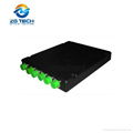
| Model: | - |
|---|---|
| Brand: | ZG TECH |
| Origin: | - |
| Category: | Electronics & Electricity / Optical Fiber, Cable & Wire / Optical Fiber |
| Label: | AAWG , MUX DEMUX AAWG , 100G MUX DEMUX AAWG |
| Price: |
US $550
/ pc
|
| Min. Order: | 1 pc |
Product Description
Product Description
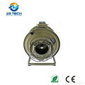
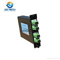
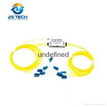
ZG TECH offers a full range of Thermal/Athermal AWG products, including 50GHz, 100GHz and 200GHz Thermal/Athermal AWG. Here we present the generic specification for the 48-channel 100GHz Gaussian Athermal AWG (48 channel AAWG) MUX/DEMUX component supplied for use in DWDM system.
Athermal AWG(AAWG) have equivalent performance to standard Thermal AWG(TAWG) but require no electrical power for stabilization. They can be used as direct replacements for Thin Film Filters(Filter type DWDM module) for cases where no power is available, also suitable for outdoor applications over -30 to +70 degree in access networks. ZG TECH's Athermal AWG(AAWG) provide excellent optical performance, high reliability, ease of fiber handling and power saving solution in a compact package. Different input and output fibers, such as SM fibers, MM fibers and PM fiber can be selected to meet different applications. We can also offer different product packages, inluding special metal box and 19” 1U rackmount.
The planar DWDM components(Thermal/Athermal AWG) from Flyin Optronics are fully qualified according to Telcordia reliability assurance requirements for fiber optic and opto-electronic components (GR-1221-CORE/UNC, Generic Reliability Assurance Requirements for Fiber Optic Branching Components, and Telcordia TR-NWT-000468, Reliability Assurance Practices for Opto-electronic Devices).
Typical Advantage
1. Multiplexing of up to 4 Channels on a single fiber
2. HIgh quality thin film filter technology
3. 100GHz ITU grid,0.8nm spacing
4. Low Insertion Loss
5. Simplex LC/UPC for line port
Typical Usage
1. Channel ADD/DROP
2. DWDM Network
3. Wavelength Routing
4. Fiber Optical Amplifier
5. CATV Fiber Optic System
Performance Specifications
|
NO. |
PARAMETER |
SPECIFICATION |
UNITS |
NOTE |
||||
|
MIN. |
TYP. |
MAX. |
|
|||||
|
2.1 |
Channels |
41 |
Ch |
|
||||
|
2.2 |
Channel Spacing |
100 |
GHz |
|
||||
|
2.3 |
Reference Passband |
±12.5 |
|
±12.5 |
GHz |
Centered at each ITU channel frenquency,Fc |
||
|
2.4 |
Wavelength Accuracy |
-50 |
|
+50 |
pm |
Offset from ITU grid over operation temperature range |
||
|
2.5 |
Center Wavelength Slope |
|
|
1 |
pm/°C |
Average slope of CW change with temp. |
||
|
2.6 |
1dB Bandwidth |
0.38 |
0.4 |
|
nm |
1dB from min Insertion Loss, full width,unpolarized |
||
|
2.7 |
3dB Bandwidth |
0.58 |
0.6 |
|
nm |
3dB from min Insertion Loss, full width,unpolarized |
||
|
2.8 |
20dB Bandwidth |
|
|
1.26 |
nm |
20dB from min Insertion Loss, full width,unpolarized |
||
|
2.9 |
30dB Bandwidth |
|
|
1.76 |
nm |
30dB from min Insertion Loss, full width,unpolarized |
||
|
2.10 |
Insertion Loss |
|
|
6.0 |
dB |
Maximum of the insertion loss across within reference passband over all channels, including connector loss |
||
|
2.11 |
Insertion Loss Uniformity |
|
|
1.5 |
dB |
Loss uniformity among channels at ITU center |
||
|
2.12 |
Ripple |
|
|
0.5 |
dB |
Maximum of the loss variance across the reference passband over all channels |
||
|
2.13 |
Adjacent Channel Isolation |
23 |
|
|
dB |
Ratio of peak transmission to the maximum transmission over both adjacent passbands,at ITU grid frequency |
||
|
<![if !supportLists]>2.14 <![endif]> |
Non-adjacent Channel Isolation |
30 |
|
|
dB |
Ratio of peak transmission in channel passband to the maximum transmission over all non-adjacent passbands |
||
|
2.15 |
Total Crosstalk |
21 |
|
|
dB |
Ratio of power in channel to power in all other passbands, at ITU grid frequency |
||
|
2.16 |
Polarization Dependent Loss (PDL) |
|
|
0.5 |
dB |
Maximum insertion loss difference between all polarization states, within reference passband |
||
|
2.17 |
Return Loss |
40 |
|
|
dB |
Ratio of input power in to the reflected power out |
||
|
2.18 |
Maximum continuous optical power |
|
|
250 |
mW |
Maximum input optical power |
||
|
2.19 |
Chromatic Dispersion(CD) |
-20 |
|
+20 |
ps/nm |
Maximum change rate of group delay versus wavelength within reference passband |
||
|
2.20 |
Polarization Mode Dispersion(PMD) |
|
|
0.5 |
ps |
Averaged differential group delay within reference passband |
|
|
Member Information
| ZG TECHNOLOGY(SHENZHEN) LIMITED | |
|---|---|
| Country/Region: | Guang Dong - China |
| Business Nature: | Manufacturer |
| Phone: | 15986645319 |
| Contact: | Ms Liqin Schon (Sales) |
| Last Online: | 19 Jul, 2017 |
Related Products of this Company
-
LGX Box 8channels CWDM MUX DEMUX for 10
US $80
-
chinese manufacturer supplys ODVA(LC SC
US $60
-
Military Tactical Deployment Cart with
US $200
-
GEPON System 4 or 8Channel LGX Module
US $80
-
4,6,8,12core ODC to single Mode LC upc
US $50
-
Waterproof Single Mode 4Core ODC optic
US $500
-
Telecommunication 1*8+1 Channel Mini
US $120
-
4Core Single Mode mode FTTA RRU BBU Base
US $150
-
ABS Module 4CH CWDM OADM MUX DEMUX OADM
US $50
-
2 Core Socket and Plug ODC to FC APC
US $60


