New insert type spring clamp chuck

| Model: | - |
|---|---|
| Brand: | - |
| Origin: | Made In China |
| Category: | Industrial Supplies / Machine Hardware / Mold |
| Label: | Hardware mould , Plastic mold , Die casting mold |
| Price: |
-
|
| Min. Order: | - |

Product Description
Foreword
The collet chuck for processing the bearing ring is usually an integral structure, but in the long-term use process, when the chuck wears more than a certain limit, the phenomenon of clamping the workpiece will appear, which directly affects the processing accuracy and production efficiency, and even the collet chuck scrapped. To improve the wear resistance of the chuck, it is necessary to increase the hardness of the chuck. If the hardness of the chuck is too high, the elasticity of the chuck is weakened and the spring flap is easy to break. To this end, an insert spring chuck is designed to solve this problem.
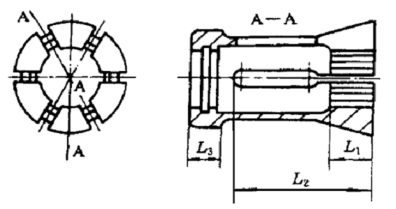
Figure 1 Integral spring chuck structure
Second, the improvement of the spring chuck
The structure of the insert-type spring chuck is shown in the following figure. It is composed of two parts, one is the chuck body, and the other is the clamp block, and the two are connected by screws. The chuck body has six spring flaps, and the clamping and unclamping action is completed by the elastic deformation of the spring flaps when working. The material of the chuck body is 65Mn, and the quenching hardness is 40~45HRC to ensure the elasticity of the chuck; and the clamping block is installed The claws of the chuck are in direct contact with the workpiece. The clamping block is an easy to wear part. The clamping block material can be GCr15 with a quenching hardness of 60~62HRC to increase wear resistance. The following problems have occurred in the use of insert spring chucks:
(1) Since the chuck manufacturing error is prone to eccentricity, the wall thickness difference of the ferrule after turning will appear.
(2) After the clamping block is arbitrarily installed in the chuck, the roundness of the clamping block is not good. If the ferrule is clamped with such a clamping block, the wall thickness difference of the processed ferrule will also be out of tolerance. Must find a way to overcome it when manufacturing.
Figure 2 Inserted collet chuck
1-chuck 2-block
Third, the machining accuracy of the clamp body and the clamp head is guaranteed
3.1 The conical surface of the fine turning chuck, using threaded tires to ensure the machining accuracy
After finishing each surface of the chuck body, and after drilling the equally divided holes, turn the tapered surface. When turning the tapered surface, use the threaded surface as the positioning reference, and design a threaded tire, which can ensure the machining accuracy of the tapered surface. . The processing principle is as shown in the figure below. First, screw the chuck onto the threaded tire, then install the threaded tire on the spindle of the machine tool, and finally use the small tool holder on the pallet to cut.

Figure 3 Schematic diagram of turning the outer cone of the chuck
3.2 Milling equal slots
When milling the sub-slots on the chuck, first use an end mill to mill a 20 mm×40 mm six-equal groove, and then use a piece milling cutter to mill a 3 mm-wide six-equal narrow groove for the split, but this groove It cannot be milled through, and there are 3~4 mm ribs on the end face, so that the chuck body is still integral, to ensure that the chuck is not deformed after heat treatment and the machining accuracy of each positioning surface of the chuck is ground. The processing principle is as follows:
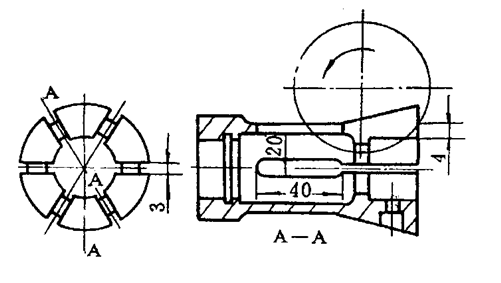
Figure 4 Processing principle of chuck positioning surface
After the above processing, the clamps should be heat treated, but the treated parts should be reasonable. The head and tail of the chuck need to be quenched, and the hardness is about 40~45HRC. The middle part of the chuck is not quenched to ensure the elasticity of the chuck.
3.3 Grinding the conical surface of the chuck
When grinding the tapered surface of the chuck, threaded tires are also used to ensure the grinding accuracy. The tapered surface is an important positioning surface in the clamping process of the chuck. The accuracy of the tapered surface directly affects the accuracy of the entire chuck. A set of threaded tire clamping chucks for grinding is designed, and the positioning reference is still to choose the thread. The grinding principle is as shown in the figure below. The conical surface after grinding can reach 0.1mm coaxiality with respect to the threaded surface.
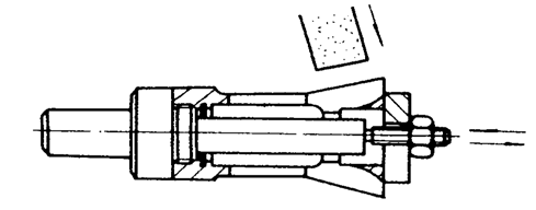
Figure 5 Grinding principle of conical surface
3.4 Grinding the inner diameter of the chuck
The inner diameter of the tire is ground to ensure the accuracy of the grinding process. The inner diameter of the chuck is also a positioning surface. The inner diameter of the chuck is used to clamp the clamping block, and then the clamping block is used to clamp the workpiece, so the accuracy of the inner diameter also directly affects the accuracy of the processed workpiece. This requires the inner diameter and the conical surface to be coaxial. We design a special grinding inner diameter mold clamping chuck. This tire is positioned on a conical surface. The grinding principle is as shown in the figure below. After grinding, the coaxiality of the inner diameter of the chuck relative to the conical surface is generally up to 0.02mm. The head of the chuck is cut into six petals, and then it is tempered to enlarge.
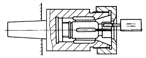
Figure 6 Grinding principle of the inner hole of the chuck
3.5 Grinding chuck guide surface
The threaded tire is also used to ensure the grinding accuracy. The guiding surface plays a guiding role in the chuck, and the guiding surface and the conical surface must be coaxial. The threaded tire clamping chuck used when grinding the conical surface is still used. The grinding principle is as shown in the figure below. The coaxiality of the ground guide surface relative to the conical surface can reach 0.04 mm. The accuracy of the chuck is achieved through the above five parts of the processing technology and guarantee measures, but the accuracy of the clamping block installed in the chuck directly affects the accuracy of the entire chuck.
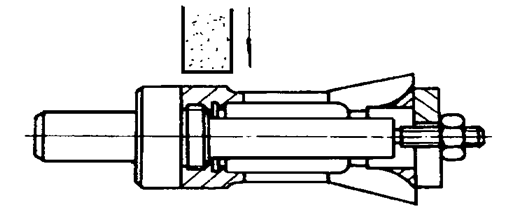
Figure 7 Grinding principle of the guide surface of the chuck
Fourth, the processing technology of the block
4.1 Milling equal parts
Since the chuck body is six-lobed, the clamping block is also a group of six-lobes. When milling a six-part opening, the mouth is not milled through at first, and there are 3~4 mm ribs in the radial direction, so that there are six clamping blocks in a group. It is still one piece to ensure the same size and accuracy of a set of clamps during grinding after quenching. The milling principle is shown in the figure below, and it can mill five to six workpieces at a time. Mark the specifications and group numbers for each set of clamping blocks, and then mark the sequence numbers for each block in each group in sequence. The clamping block material is made of bearing steel, and the quenching hardness is generally 60~62HRC.
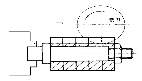
Figure 8 Milling principle of the six-point slot of the card block
4.2 diameter grinding
It is required that the inner and outer diameters of each group of blocks must be coaxial. Firstly, grind the inner diameter. When grinding a batch of jobs, the inner diameter should be the same size, and then the outer diameter. When grinding the outer diameter, use the inner diameter to position to ensure that the inner and outer diameter are coaxial. We design a mandrel with a length of 150mm and a taper difference of 0.02~0.03mm. First insert the workpiece tightly on the mandrel, then put the mandrel on top, and finally grind the outer diameter on a universal grinder. The grinding principle is as shown in the figure below. After grinding, the inner and outer diameters of the clamping block are coaxial. 0.02 mm.
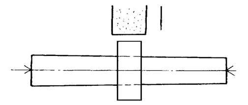
Figure 9 Principle of Grinding the Outer Diameter of the Block
4.3 Cut the six petals and remove the burrs. The center positioning accuracy of the insert chuck depends on the manufacturing accuracy of the chuck body and the chuck, and the following points should be paid attention to:
(1) When changing specifications, only the clamp block is replaced, not the chuck body; only the clamp block is replaced when the chuck is worn out.
(2) The card blocks must be divided into 6 groups, kept in groups, used in groups, and not mixed.
(3) When installing the clamp block, it must be arranged in sequence number, otherwise the accuracy of the clamp block itself will be damaged, and the wall thickness difference of the ferrule after turning will be out of tolerance.
Conclusion
Aiming at the original integrated spring chuck structure, the innovative design of the insert block ensures the processing flexibility while improving the accuracy of the chuck. At the same time, the processing technology has been improved in detail. This solution is used to manufacture the fixture. It can greatly reduce manufacturing cost and processing difficulty, reduce unnecessary waste of materials, improve production efficiency, and bring huge economic benefits.


Member Information
| Huizhou Shunqiang Electronics Co., Ltd | |
|---|---|
| Country/Region: | Guang Dong - China |
| Business Nature: | Manufacturer |
| Phone: | 13715334662 |
| Contact: | Kennethchui (Engineer) |
| Last Online: | 03 Feb, 2024 |
Related Products of this Company
-

Stamping is based on the press and die
-

12 sets of mold structure diagram
-

Dynamic diagram of how to demold a
-

Metal mold stamping process
-

3 sets of classic mold structure
-

A set of mold design ideas and processes
-

Slider out of the slider
-

Automobile air conditioner shell mould
-

Mold vacuum heat treatment technical
-

Automobile air conditioner shell mould