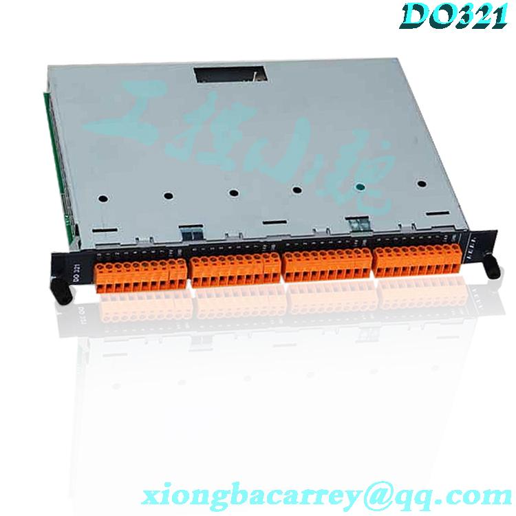
KEBA FB201 FB201 CP450/C CP450 IP706 OP341/Y-1400 CP033/Y AR281 SI232 PS244 EC100S DO321 DI325 DI325 DI325 CU313A CU313 CU312/E cable connectors are terminated on two adjacent substrates, forming a single cable (see Figure 1, page 4). Single terminated cables from redundant adapters to related termination components (TA). In case of redundancy, any module can be replaced to a good module without disturbing the field input signal. Each module can remove/replace terminal wiring, power supply, VALMET 421907-1B VALMET A413045 VALMET A413052 VALMET A413285 VALMET A413295 VALMET CPR1 A413280 VISHAY 120NQ045R VMIC VMIVME Model 2533 Assy No 332-002533-010E VMIC ZT5524A1A MCS SA1000 MECS CPU-1000 MECS EXT-1 MECS EXT-2 MECS UTV-F2500HA MECS UTX-1000A MECS UTX1010 IDEC PF3S-BP13 IDEC PF3S-HSC1 IDEC PF3S-T32K IDEC PFJ-T081U IDEC RU4S-D24 IDEC SY4S-05D IDER ABW140EG DIGIFAS DIGIFAS7105 DIGIFAS DIGIFAS7108 DIGIFAS DIGIFAS7116 ELAU MC-4/11/01/400 ELAU MC-4/11/03/400 ELAU PMC-2/11/08/000/00/03/11/00/0K ELAU C600/10/1/1/1/00 KEBA FB201 FB201 CP450/C CP450 IP706 OP341/Y-1400 CP033/Y AR281 SI232 PS244 EC100S DO321 DI325 DI325 DI325 CU313A CU313 CU312/E VALMET 421907-1B VALMET A413045 VALMET A413052 VALMET A413285 VALMET A413295 VALMET CPR1 A413280 VISHAY 120NQ045R VMIC VMIVME Model 2533 Assy No 332-002533-010E VMIC ZT5524A1A MCS SA1000 MECS CPU-1000 MECS EXT-1 MECS EXT-2 MECS UTV-F2500HA MECS UTX-1000A MECS UTX1010 IDEC PF3S-BP13 IDEC PF3S-HSC1 IDEC PF3S-T32K IDEC PFJ-T081U IDEC RU4S-D24 IDEC or communication wiring without removing fields. Modular substrate installation FBM240 modules can accommodate up to four or eight FBMs when installed on modular substrates mounted on DIN rails. The modular substrate is installed on DIN rails or racks, including signal connectors for redundant modules, fieldbus, redundant independent DC power supplies, and terminal cables. Redundant modules must be located on the substrate (positions 1 and 2, 3 and 4, 5 and 6, or 7 and 8). To achieve redundancy, a redundant adapter module is placed on two adjacent backplanes to provide a single terminated cable connector (see Figure 1). For system configurator applications and other systems monitored through SMON, Foxboro DCS system manager and SMDH, redundant FBM240s appear to be independent non redundant modules. The functional redundancy of these modules is provided by their associated control blocks. The redundant modules in Foxboro DCS HMI are two independent module management software applications for the system, such as Foxboro DCS System Manager and System Manager/Display Processing Program (SMDH). These functional redundancy modules are provided by their associated control blocks. The on-site I/O signals of the terminal components are connected to the FBM subsystem components (TA) through DIN rail installation terminals. The TA used with FBM240 provides: ? Output signal connection points ? External power connection points ? Each output 5 A unsealed relay or 10 A unsealed relay ? 15-60 V DC switch and voltage monitor input relay TA has a high voltage input circuit for monitoring the contacts of each output relay. The monitor circuit is a component installed on the TA on the daughter card. Each TA has two sub cards, each with four monitoring circuits. TA is: ? 80 to 125 V DC at RH917YF-5 A or 80 to 120 V AC at 10 A ? 80 to 120 V AC at RH917HU-5 A ? RH926SZ-15 to 30 V DC at 5 ARH916AQ/RH916AR-15 to 60 V DC voltage monitor and 2 A switch. Note: When the FBM240 output is disconnected, the TA contact remains oriented as described in Tables 2 and 3. RH916AQ/RH916AR passive TA provides fused 2A output and independent input for 15-60 V dc. The redundant adapter connects the redundant FBM substrate connectors together. Redundant adapters provide a single terminal connection to a single TA. The terminal components installed on the DIN rail are connected to the redundant adapter through detachable terminal cables in the following way. This cable has multiple lengths, up to 30 meters (98 feet), allowing terminal components to be installed in the same enclosure or adjacent enclosures. The front of the visual indicator module integrates red and green light-emitting diodes (LEDs) to provide visual status indication of FBM functionsSY4S-05D IDER ABW140EG DIGIFAS DIGIFAS7105 DIGIFAS DIGIFAS7108 DIGIFAS DIGIFAS7116 ELAU MC-4/11/01/400 ELAU MC-4/11/03/400 ELAU PMC-2/11/08/000/00/03/11/00/0K ELAU C600/10/1/1/1/00 KEBA FB201 FB201 CP450/C CP450 IP706 OP341/Y-1400 CP033/Y AR281 SI232 PS244 EC100S DO321 DI325 DI325 DI325 CU313A CU313 CU312/E VALMET 421907-1B VALMET A413045 VALMET A413052 VALMET A413285 VALMET A413295 VALMET CPR1 A413280 VISHAY 120NQ045R VMIC VMIVME Model 2533 Assy No 332-002533-010E VMIC ZT5524A1A MCS SA1000 MECS CPU-1000 MECS EXT-1 MECS EXT-2 MECS UTV-F2500HA MECS UTX-1000A MECS UTX1010 IDEC PF3S-BP13 IDEC PF3S-HSC1 IDEC PF3S-T32K IDEC PFJ-T081U IDEC RU4S-D24 IDEC SY4S-05D IDER ABW140EG DIGIFAS DIGIFAS7105 DIGIFAS DIGIFAS7108 DIGIFAS DIGIFAS7116 ELAU MC-4/11/01/400 ELAU MC-4/11/03/400 ELAU PMC-2/11/08/000/00/03/11/00/0K ELAU C600/10/1/1/1/00


