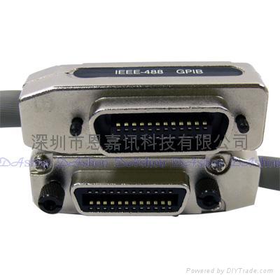
IEEE-488 Overview System & Active Controllers Listeners, Talkers and Controllers Interface Signals Data Lines Handshake Lines Handshaking Interface Management Lines Device Addresses Physical Characteristics Summary –
The IEEE-488 bus was developed to connect and control programmable instruments, and to provide a standard interface for communication between instruments from different sources. Hewlett-Packard originally developed the interfacing technique, and called it HP-IB. The interface quickly gained popularity in the computer industry. Because the interface was so versatile, the IEEE committee renamed it GPIB (General Purpose Interface Bus). –
IEEE-488 Overview Almost any instrument can be used with the IEEE-488 specification, because it says nothing about the function of the instrument itself, or about the form of the instrument's data. Instead the specification defines a separate component, the interface, that can be added to the instrument. The signals passing into the interface from the IEEE-488 bus and from the instrument are defined in the standard. The instrument does not have complete control over the interface. Often the bus controller tells the interface what to do. The Active Controller performs the bus control functions for all the bus instruments. –
System Controller & Active Controller At power-up time, the IEEE-488 interface that is programmed to be the System Controller becomes the Active Controller in charge. The System Controller has several unique capabilities including the ability to send Interface Clear (IFC) and Remote Enable (REN) commands. IFC clears all device interfaces and returns control to the System Controller. REN allows devices to respond to bus data once they are addressed to listen. The System Controller may optionally Pass Control to another controller, which then becomes Active Controller. –
Data Lines The lines DIO1 through DIO8 are used to transfer addresses, control information and data. The formats for addresses and control bytes are defined by the IEEE 488 standard. Data formats are undefined and may be ASCII (with or without parity) or binary. DIO1 is the Least Significant Bit (note that this will correspond to bit 0 on most computers). -
Three Shields Plus Cast Aluminum Shells - Two foil shields plus one copper braid shield (over 90% coverage) provide low capacitance to maintain the IEEE specifications of these cables. Designed and built to handle your system’s data rate, up to the 1 Mbyte/s IEEE maximum. All technical features found in our Premium CIB24 Series are incorporated in this series, the only exception is one less shield.-
Double Shielded with Molded Backshells - L-com offers many IEEE-488 cable assembly options. The most economical choice uses double shielded cable that is adequate for many applications. Featuring all-molded connector ends which contribute to a long life expectancy and are impervious to breakage at the point where the cable enters the connector housing. A unique stamped steel internal enclosure provides 100% shielding and a robust strain relief.--
These innovative bulkhead adapters allow the user to pass GPIB cables through a panel or enclosure. Utilizing a unique steel/nickel plated mounting flange and cast aluminum connector housing, these adapters are built to last. Choose from either female to female or male to female versions. A fiberglass insulated female to female version also exists for users concerned with ground loops.-
Wide selection of used semiconductor equipment and electronic test manufacturing equipment and more -– industrial equipment, semiconductor equipment, used industrial equipment, electronic test equipment and used semiconductor equipment and used electronic equipment from Equipment Exchange!
Interface Signals The IEEE-488 interface system consists of 16 signal lines and 8 ground lines. The 16 signal lines are divided into 3 groups (8 data lines, 3 handshake lines, and 5 interface management lines). –


