| Model: | BHL25-20 |
|---|---|
| Brand: | BH |
| Origin: | Made In China |
| Category: | Industrial Supplies / Construction Machine |
| Label: | Backhoe Excavator-Lo , Backhoe Loader |
| Price: |
-
|
| Min. Order: | 1 pc |
Product Description
It has the following characteristics:
1. It uses hydromechanical drive, which consists of a hydraulic torque converter and a dynamic gear case. Since the torque converter well matches with engine and engine power can be best utilized, the vehicle is featured with better traction, high speed, excellent accelerating ability and high operating efficiency.
It has the following advantages to drive by hydraulic torque converter:
(1) The loader can be automatically adjusted. As external load gets abruptly increasing, the traction is automatically increased to moderate such load and prevent the engine from stalling. On the contrary, as external load is decreasing, the vehicle can reduce traction to speed up. (2) Because hydraulic drive works by liquid that can absorb and eliminate vibration and shock from engine and eternal load, the engine and transmission system are well protected, and life of loader is prolonged. (3) The loader can start steadily, and stepless change speed, by which vehicle becomes comfortable and operation becomes simple.
The dynamic gear case is dead axle one, simple and compact in structure, convenient on maintenance, easy and steady on gearshift. By combined with hydraulic torque converter, transmission system has a broad transmission range with ideal efficiency.
2. Due to adopting articulated carriage and full-hydraulic steering system, the vehicle turns around flexibly in small turn radium and excellent performances.
3. Operating unit with eight link rods designed with computer is featured with larger digging force, rapid operation and high efficiency.
4. Because brake system uses vacuum augmenter, braking reliability is enhanced and pedal force is reduced to meet with different driving conditions.
Hydraulic system preset and quick-change coupler for digger unit can rapidly couple breaking hammer, earth borer, slag remover and sling. If necessary, you could replace loading bucket with snow blade, road surface planner, blender and fork to satisfy different working requirements.
Unit II Specifications
1. Total length (bucket horizontally lying on ground) (mm) 6500
2. Total Width (Width of Bucket) (mm) 2060
3. Total Height (mm) 3300
4. Wheel Base (mm) 2140
5. Wheel Span (mm) 1560
6. Distance from carriage linkage point to front axle (mm) 1200
7. Max. carriage deflection angle (left, right) 35°
8. Min. ground clearance (mm) 285
9. Rear overhang (mm) 1210
10. Leave angle 25°
11. Dirve speed
First Gear (Forward) (km/h) 0~11
(Backward) (km/h) 0~10
Second Gear (Forward) (km/h) 0~27
(Backward) (km/h) 0~26
12. Uphill angle 25°
13. Min. turning radius (front wheel center) (mm) 4190
II. Rear Digger unit
1. Capacity of bucket (m3) 0.25
2. Max. Digging depth (mm) 4100
3. Max. Digging radium (mm) 5000
4. Max. Dumping height (mm) 3130
5. Unloading distance (to center of turning circle) 1800
6. Max. Digging force (kN) 36
III. Front operating unit
1. Capacity of bucket (m3) 0.9
2. Rated loading mass (t) 1.6
3. Digging force (kN) 50
4. Max. Traction (kN) 38
5.Unloading height (when unloading angle at 45°)(mm) 2600
6. Unloading distance ( when unloading angle at 45°)(mm) 880
7. Bucket return angle 48°
8. Unloading angle 45°
9. Digging depth (mm) 220
10. Working time of operating unit
Lifting time (rated load in bucket)(s) 5
Dropping time (no load)(s) 3.2
Forerake time (no load)(s) 1
IV. Engine
1. Model 4102
2. Type 4-stroke, water cooling, jet diesel
3. Rated power (kW) 50
4. Rated rotate speed(r/min) 2400
5. Max. torque N·m(1500r/min) 241
6.Fuel consumption rate(g/kw·h) 224
7.Oil consumption rate (g/kw·h) ≤2.5
8.Compression ratio 17:1
9. Number of cylinders 4
10. Cylinder dia.*stroke (mm) φ102 *118
11. Delivery capacity (L/R) 3.857
12.Operating order of cylinders 1—3—4—2
13. Rotate direction of crankshaft (see from flywheel end) counterclockwise
14. Mode of Start Electrical
15. Lubrication Compulsive splash
16. Generator (with vacuum pump)(W) 500
17.Starter (QD231) 24V,2.2KW
18. Air filter double-stage, air rotational flow, paper filter core
V. Transmission System
(I) Torque converter
1. Type single-stage, single-phase, 3 elements
2. Max torque ratio 2.85
3. Max. Efficiency 0.842
4. Cooling system air cooling
(II) Gear case
1. Type Dynamic dead-axle shift
2. Speed ratio:
First gear forward 2.159
Second gear forward 0.768
First gear backward 2.207
Second gear backward 0.785
(III) Axles & tires
1. Drive system 4-wheel
2. Swing angle of rear axle ±12°
3. Tire (front, rear pressure) (MPa) 0.21
4. Section width of tire (mm) 410
5. Exterior dia. of tire (mm) 1075
6. Rim 13-20(SDC)
VI. Brake System
1. Foot brake double-pipeline, vacuum boost, 4-disc brake
2. Parking brake Mechanical brake shoe
VII. Steering System
1. Type Load sensor full-hydraulic turning
2. Steering gear BZZ5-200/FKS
3. Steering oil cylinder WZ25-20.9.4H
4. Steering oil cylinder parameters (No. of cylinder-cylinder dia×column dia.*stroke) (mm) 2-φ50*φ25*265mm
5. Rated pressure (Mpa) 16
6.Turning angle ±35°
VIII. Hydraulic System for Operating Unit
1. Type with 8 link rods
2. Oil pump
Type (single-key, left rotate) CB-KP50-HF
Flow(L/min) 90
3. Main oil pump pressure (Mpa) 17.5
4. Oil cylinders of movable arm (number-cylinder dia×column dia.)(Mm)
2-φ80×φ45
1-φ110×φ55
5.Oil cylinders of skip bucket (number-cylinder dia×column dia.)(Mm)
2-φ63×φ40
6. Oil cylinders of excavator bucket (number-cylinder dia×column dia.)(mm)
1-φ90×φ45
7. Oil cylinders of bucket bar (number-cylinder dia×column dia.)(mm)
1-φ100×φ55
8. Multiday change valve VDL20.3
9. Priority valve YXL-F160L-N7
IX. Electric System
1. Rated voltage (V) 24
2. Battery N70S
3. Power for engine (W) 500
4. Power for start motor (kW) 2.2
5. Air conditioner KGWZ-40
X. Oil Charge
1. Fuel for diesel (L) 70
2. Lubrication for diesel (L) 8.5
3. Oil for hydraulic torque converter gear case (L) 15
4. Oil for hydraulic system (L) 100
5. Lubrication for each axle (L) 10
6. Oil for brake system (kg) 1.5
Unit III General Structure
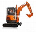
BHL 25-20 Excavator-Loader consists of diesel, chassis, loading, digging and electric systems.
1. Diesel
The vehicle adopts 4102 type diesel that drives vehicle via transmission system in chassis and drives operating unit via hydraulic system. As to its structure, specifications, application and maintenance, please read Diesel Instrument Book provided with vehicle.
2. Chassis
Chassis is the basis of the whole machine with a diesel and operating unit installed on it.
The chassis consists of driving, walking, steering, braking and other systems.
2.1 Transmission system consists of hydraulic torque converter, gear case, propeller shaft, front and Rear transaxles, transferring power from diesel to drive wheel.
2.2 Walking system consists of carriages and wheels, for bearing of components of chassis and guarantee of driving of Excavator-Loader.
2.3 Steering system consists of priority valve, steering gear and turn oil cylinder for turn of Excavator-Loader in driving.
2.4 Braking system consists of brake and driving unit for rapidly speed-down of Excavator-Loader to stop.
3. Operating unit
Operating system consists of bucket, movable arm and oil cylinders for shoveling and loading materials. The operating unit is at most front end of Excavator-Loader.
4. Digger unit
The digger unit is at rear end of Excavator-Loader, and consists of bucket, movable arm, bucket bar and oil cylinders, for excavating. It can reversely rotate 180°.
5. Electric system
Electric system consists of generator, starting motor, battery and air-conditioner (BHL 25-20B) for starting engine and providing power supply to instruments and lighting system.
Table 2-1 Control Mechanism and Instruments Functions
|
No.
|
Designation
|
Operation and Function
|
|
1
|
Brand Name
|
MAYATSTAR/ B.H.GROUP
|
|
2
|
Time Counter
|
For counting total operating time of vehicle. Time counter is synchronizing with engine, and counts when vehicle works.
|
|
3
|
Pressure meter at torque converter inlet
|
Show oil pressure at inlet of torque converter. At normal operation, oil pressure shall range 0.5~0.7Mpa.
|
|
4
|
Shift pressure gauge of gear case
|
Show oil pressure controlling shift. At normal operating, oil pressure shall range 1.2~1.4Mpa.
|
|
5
|
Left-turn indicator
|
It indicates left-turn lamp of vehicle is power on when the indicator lights.
|
|
6
|
Charge indicator
|
It indicates the battery isn’t at charging state when the indicator lights, and indicates the battery is at charging state when the indicator doesn’t light.
|
|
7
|
Shift pressure indicator of gear case
|
As oil pressure for gearshift is insufficient, the indicator lights.
|
|
8
|
Fuel gauge
|
It is used to show fuel level reserved in fuel tank.
|
|
9
|
Braking indicator
|
As vehicle is braking at driving and working, the indicator lights.
|
|
10
|
Right-turn indicator
|
It indicates right-turn lamp of vehicle is power on as the indicator lights.
|
|
11
|
Oil temperature gauge of torque converter
|
For observing oil temperature at outlet of hydraulic torque converter, which shall be below 110℃ at normal operating.
|
|
12
|
Engine water temperature meter of engine
|
It indicates leaving water temperature of engine. Water temperature at normal operating shall be below 90℃.
|
|
13
|
Voltmeter
|
Voltage is 24V~32V at driving and 24V at stopping.
|
|
14
|
Accelerator pedal
|
For control of engine throttle.
|
|
15
|
Steering wheel
|
For control of driving direction. You could operate it with one hand through crank attached to the wheel.
|
|
16
|
Horn and turn switch
|
The horn is on the top of the handle, the horn is switched on by pressing the handle, and shuts off by releasing the handle. When the handle is pushed forward, the left-turn lamp lights, and when the handle is pulled back, the right-turn lamp lights.
|
|
No.
|
Designation
|
Operation and Function
|
|
17
|
Start switch
|
Insert key, turn clockwise to I-gear to switch main power on, electric system works; then turn a gear clockwise, diesel engine starts. (When steering handle lies at neutral position.)
|
|
18
|
Fuse block
|
Fuses are used to maintain normal operation of whole electric system.
|
|
19
|
Control lever of operating unit
|
Operating unit stays in hold state when lever is at neutral position; it gets bucket retracted when lever is moved left from neutral position; it gets bucket dumped when lever is moved right from neutral position; it gets movable arm lifting when lever is pulled back from neutral position; it gets movable arm descending when lever is pushed forward to I-gear from neutral position; and it remains movable arm floating when the lever is pushed forward to II-gear from neutral position.
|
|
20
|
Tie rod for stalling
|
As rod is pulled out, engine stalls. The rod shall be moved to its initial position after engine stalls.
|
|
21
|
Control handle of hand throttle
|
For control of engine throttle.
|
|
22
|
Control lever of manual brake
|
For parking brake. Vehicle brakes when lever is drawn back. Braking force is directly proportional to control force. It is used for control of engine throttle.
|
|
23
|
Oil-return filter
|
Filter element can be replaced by removing cover.
|
|
24
|
Control lever of left support leg
|
For extension and retraction of left support leg. The support leg stays at hold state when lever is at neutral position; When lever is pushed forward, the leg extends; when lever is pulled back, the leg retracts.
|
|
25
|
Movable arm lever and turn-around lever
|
For rising and dropping of movable arm and turn-around of digger unit. They are in hold state when lever lies at neutral position; the arm drops down when lever is moved forward; the arm rises up when lever is pulled back; excavating system turns left when the lever is moved left; and excavating system turns right when lever is moved right.
|
|
26
|
Control lever for bucket and bucket bar
|
For adjusting bucket’s digging and dumping as well as extension and retraction of bucket bar. They stays in hold state when lever lies at neutral position; when lever is pushed forward, the bucket dumps; when lever is pulled back, the bucket retracts; when lever is moved left, the bucket bar retracts; when lever is moved right, the bucket bar extends.
|
|
No.
|
Designation
|
Operation and Function
|
|
27
|
Oil cylinder for right support leg
|
For extension and retraction of right support leg. The leg keeps in hold state when the cylinder lies at neutral position; the leg stretches out when the cylinder is pushed forward; and the leg retracts when the cylinder is pulled back.
|
|
28
|
Filling port for hydraulic oil
|
Remove cover and refill hydraulic oil.
|
|
29
|
Seats
|
Direction and forward-backward positions of seats can be adjusted as required.
|
|
30
|
Three-gear lighting switch
|
For adjusting lighting. Front and rear side marker lamps light when the switch is at I-gear backward; head lamp is low beam and rear side marker lamp lights when the switch is at II-gear backward; head lamp high lights and rear side marker lamp lights when the switch is at III-gear backward.
|
|
31
|
Steering shift lever
|
For changing driving direction of vehicle. Vehicle stays at neutral position when the lever lies at neutral position, goes forward when the lever is pushed forward, and goes backward when the lever is pulled backward. I mean I-gear; II means II-gear.
|
|
32
|
Brake pedal (stop power braking)
|
For traveling brake. When pedal is depressed, vehicle brakes and power from engine to transaxle is cut.
|
Member Information
| Beijing Mayastar Machinery & Electrical Equipment Co., Ltd | |
|---|---|
| Country/Region: | Beijing - China |
| Business Nature: | Trading Company |
| Phone: | 13716094260 |
| Contact: | zhangcare (sales assistant) |
| Last Online: | 16 Jan, 2014 |


