| Model: | APX901 |
|---|---|
| Brand: | ai pu xin |
| Origin: | Made In China |
| Category: | Electronics & Electricity / Electronic Instrument / Electronic Measurment Apparatus |
| Label: | High-precision magne |
| Price: |
¥1700
/ pc
|
| Min. Order: | 1 pc |
| Last Online:29 Jul, 2020 |

working principle
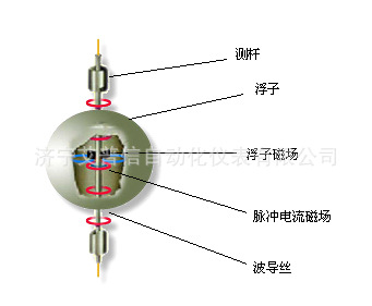
Magnetostrictive liquid level sensor consists of stainless steel tube (rod), magnetostrictive wire (waveguide wire), movable float (with a permanent magnet) and other parts of the group
Into, see figure. When the sensor is working, the circuit part will excite the pulse current on the guide wire, which will generate pulsed electromagnetic wave around the guide wire when it propagates along the guide wire
field. In the sensor rod equipped with a float, the float along the spindle along with the level changes and up and down movement. Inside the float there is a permanent magnet ring. When pulsed current magnetic field
When the magnetic field generated by the float encounters a magnetic field, the magnetic field around the float changes so that the guide wire made of magnetostrictive material produces a
Torsional wave pulse, the pulse at a fixed speed along the waveguide wire back and detected by the detection mechanism. By measuring the pulse current and torsional wave time difference can be accurately determined
The location of the float, the level of the liquid.
Technical Parameters
Power supply: 24V ± 2.4V. DC
Operating temperature: Electronic warehouse:
T1 grade: -40 ℃ ~ +80 ℃;
T2 level: -25 ℃ ~ +70 ℃;
T3 grade: -10 ℃ ~ +65 ℃;
T4 grade: 0 ℃ ~ +70 ℃;
Measuring rod: -40 ℃ ~ + 110 ℃;
The main technical performance indicators
a) Range: Hard rod: 150mm ~ 7000mm, soft rod: the longest 16000mm;
b) Output Type: 4 ~ 20mA; 0 ~ 5V; 0 ~ 10V; ± 5V; ± 10V; RS-485
c) Linearity error: better than ± 0.05% FS; sensor with range less than 300mm with error less than 150μm
d) Repeatability: better than ± 0.002% FS
e) output temperature drift: 50ppm / ℃; f) product power consumption: ≤ 50mA;
g) Output ripple: ≤20mV;
h) dead zone: soft rod: the dead zone: 100mm, the next dead zone 300mm;
Hard rod: the dead zone: 51mm, the next dead zone: 36mm, a black line logo;
(According to user requirements appropriate changes)
i) With load capacity: 4 ~ 20mA Output: with load capacity ≤ 500Ω;
0 ~ 5V, 0 ~ 10V Output: Minimum controller load ≥ 5kΩ;
3.4 Other parameters
a) measuring rod material: 0Cr18Ni9, 1Cr18Ni9Ti or user special customization;
b) Electronic housing material: 1Cr18Ni9Ti;
c) Lead way:
1. Shielded cable connection, the default length of 1.5m (according to user requirements change);
2. Aviation plug connection;
3. Terminal connection;
d) Float material: 0Cr18Ni9,316, nitrile rubber;
e) Installation form: thread installation, connector installation, positioning ring installation, hanging installation or user-specific
f) Explosion-proof type: ExdIIBT5, ExiaIIBT5, ExdIICT5
g) Degree of protection: IP65 Method of operation
installation method
1. Thread installation
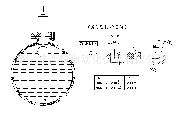
As shown in the figure, the product should be mounted vertically and the installation slope can not be more than 5 degrees. When mounting the float, the NO (top) marked hemisphere should be above the liquid level;
Zone; the lower end of the locking ring should be flush with the bottom of the rod when it is fixed.
This method is suitable for most of the tank measurement, the manufacturer can choose to use the connection flange or user-specific flange, the liquid level sensor mounting screw directly into
In the flange.
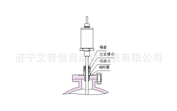
2. Use the active connector installation This method is suitable for measuring height adjustable open cans and sealed cans measurement.
3. Locating ring installation
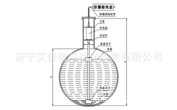
Sensor rod touch the bottom of the tank, relying on the positioning of electronic warehouse department to prevent the sensor swing, the sensor electronics and leads to the cable in the tank.
Note:
h = tank height
H = h + riser height
D = Φ100mm
Stand pipe height ≥300mm

4. Hanging installation
The sensor is hung under the flange of the tank mouth, the measuring rod and the tank bottom to maintain a certain distance (2 ~ 5mm), relying on the positioning of electronic warehouse department to prevent the sensor swing, sensing
Electronic warehouse and lead the cable in the tank.
Note:
h = tank height
Wiring method
Shielded cable connection
1, the analog output (4 ~ 20mA, 0 ~ 5V, 0 ~ 10V, ± 5V, ± 10V), the level sensor leads the way for the four-core shielded cable, the wiring is as follows:
Red line: + 24V.DC; blue / black line: power ground;
Yellow line: signal ground; green line: analog signal output
2,4 ~ 20mA two-wire system output
1) Wiring method
Red line: power is positive;
Blue / black line: negative power supply;
2) liquid crystal display
LCD display data is the percentage of the current level of the total range, accurate to a decimal point.
Over zero shows zero, more than full scale display 8888.
3) zero, full-scale adjustment
The zero point of the sensor is on the end side of the rod, full point on the side close to the electronic compartment. Place the float at the user-requested zero position and press the ZERO button
When a small arrow appears on the upper left of the LCD screen, release the button and set the zero point successfully. Put the float on the full scale point required by the user and press the FULL button. When the LCD screen
The bottom left of a small arrow, release the key, full point set successfully.
3, RS-485 output, wiring instructions are as follows:
Red line: + 24V.DC; blue / black line: power ground;
Yellow line: RS-485 A; green line: RS-485 B;
Aviation plug connection: aviation plug wiring diagram as shown
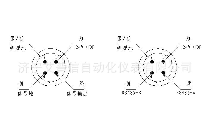
a) Analog output b) RS-485 output
Aviation plug wiring diagram (male connection surface front view)
Caution: Before wiring, please check whether the power supply meets the requirement of + 24V ± 2.4V. DC and the power output power must be greater than
The total power consumption of products, according to each sensor 50mA calculation. If the power does not meet the requirements, please replace the power supply to ensure that the sensor can work normally.
Terminal connection

Terminal connection
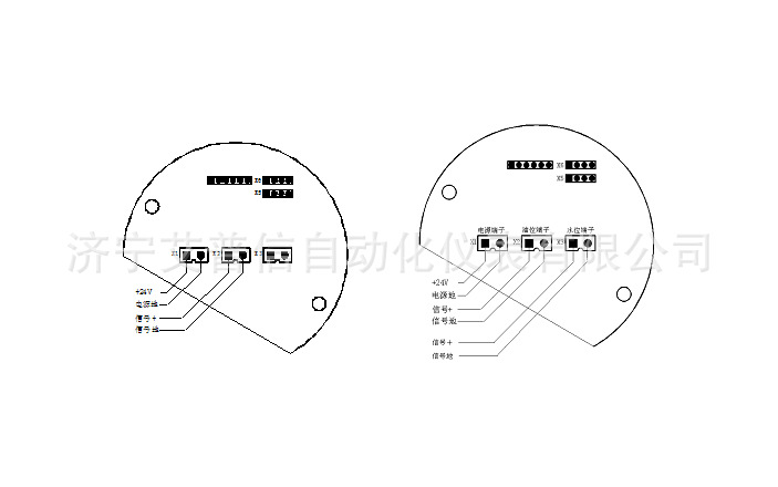
4 ~ 20mA output terminal (single float) 4 ~ 20mA output terminal (double float)
4.2.4 For the terminal products, wiring installation should pay attention to the following matters:
a. Ordinary terminal products

Loosen the compression nut of the waterproof connector of the cable and unscrew the sealing cap. The outer diameter of the cable should be Φ6 ~ 8mm, the outer layer of the cable should be stripped 15mm, the core should be stripped 5mm,
Burn the tin, the well handled cable end into the waterproof connector, in accordance with the order of connection with the terminal firmly, after the first seal cover (with o-ring) into the terminal block, tighten,
Tighten the compression nut on the cable gland to hold the cable tight. Note that the cable gland at least 10mm above the cable jacket. Please be sure to electronically
Warehouse positions fastened.
b. CE43-8 flameproof terminals
Unscrew the compression screw, unscrew the 037 case cover, select the cable diameter Φ6 ~ 8mm, the cable stripped the skin 15mm, stripping the core 5mm,
Processed cable end in turn through the compression screw, gasket, gland, adapter, in accordance with the order of the core wire and the terminal is connected firmly, after the first 037 case cover
And 037 watch case (with o-ring) tighten, and then tighten the screw into the adapter, tighten, making the gland hold the cable to ensure that the seal. Please ensure that the vaults are connected
Site fastening.
c. Two-wire intrinsically safe terminal connection

Unscrew the compression screw, unscrew the case cover (terminal end), the selection of cable diameter Φ6 ~ 8mm, the cable stripped the skin 15mm, stripping the core 5mm,
Burn the tin, will deal with the end of the cable into the compression screw, gasket, gland, adapter, in accordance with the order of the core wire and terminals connected firmly, after the first table
Tighten the cover and the case body (with o-ring), and then tighten the compression screw into the adapter, tighten, so that the sealing sleeve to hold the cable to ensure sealing. Please ensure that the vaults are connected
Site fastening.
| Payment Terms: | tt |
|---|---|