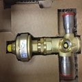
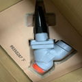
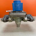
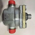
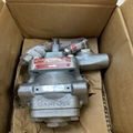
| Model: | ICS150-32-40 |
|---|---|
| Brand: | Danfoss |
| Origin: | Made In Denmark |
| Category: | Industrial Supplies / Machine Hardware / Valves |
| Label: | servo valve , pressure regulatin , Danfoss servo valve |
| Price: |
¥6688
/ pc
|
| Min. Order: | 1 pc |
| Last Online:21 Apr, 2020 |
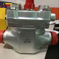
The use of Danfoss ICS150-32-40 (ICS3-65-100D) servo pressure regulator
The ICS servo main valve is a member of the ICV family of new generation industrial control valves.
ICV products
-ICS-industrial control servo valve
-ICM-industrial control electric valve
The ICS servo main valve introduces a modular design concept and consists of three modules: valve body, function module and valve cover. ICS is a main valve controlled by a pilot valve, which can be used in refrigeration systems of various pressure levels to adjust the pressure, temperature and system switching. ICS can be applied to the high / low pressure side of the refrigeration system, the wet / dry return air line, and the liquid line without phase change (such as the line without throttling and expansion). source. ICS1 has one pilot valve interface, and ICS3 has three pilot valve interfaces. The pilot valve can be installed directly on the ICS valve or on the external pilot tube. Several pilot valves can be installed in one ICS valve at the same time to realize many different adjustment functions. The valve cover of the ICS valve can be connected to a pressure gauge, which can monitor the inlet pressure of the valve body when setting or adjusting the pilot valve. The manual adjustment lever on the ICS valve end cover can manually open the main valve.
Installation method of Danfoss ICS150-32-40 (ICS3-65-100D) servo pressure regulating valve
When installing the ICS servo main valve, it is necessary to ensure that the valve stem is vertically upward (Figure 1). The ICS servo main valve must be installed in the flow direction indicated by the arrow on the valve body. The valve end cover is up (Figure 2). The end cap can be installed on the valve body by rotating four 90 ° directions without affecting the valve function. The ICS servo main valve has a manual operation lever, which can manually control the valve opening and closing. If an external pilot valve is used, the pilot valve must be connected to the upper part of the main pipe to prevent dirt and oil in the system from entering the pilot valve line.
If ICS 1 is used as a solenoid valve on the liquid supply line to control the on-off, external control pressure cannot be introduced to avoid liquid shock.
The design of ICS servo main valve can withstand high internal pressure. Nevertheless, the design of the piping system must avoid liquid traps to prevent the system from thermal expansion.
The resulting high pressure can damage the pipeline. The design of the pipeline should consider effective protection against transient "liquid strikes" in the system.
Welding (Figure 3, Figure 4 and Figure 5)
Before welding, the end cap (object 2 in Figure 4) and the functional module (object 3 in Figure 4) must be removed to prevent the O-ring and Teflon valve plate from being damaged during the welding process and can also be avoided Welding slag enters the function module. You can use an M6 bolt or a multi-tool to screw into the threaded hole on the piston to take out the functional module. If the bolt holes are blocked by foreign objects, they need to be cleaned. Note: Before welding, all parts on the valve body must be removed (as shown in Figure 5).
