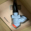
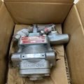
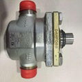
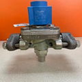
| Model: | ICAD600-900-120 |
|---|---|
| Brand: | Danfoss |
| Origin: | Made In Denmark |
| Category: | Industrial Supplies / Machine Hardware / Valves |
| Label: | Electric Actuator , Danfoss actuator , Valve actuator |
| Price: |
¥12880
/ pc
|
| Min. Order: | 1 pc |
| Last Online:21 Apr, 2020 |
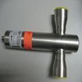
Features of Danfoss ICAD600-900-1200A (027H90775) electric actuator
ICAD 600/900/1200 driver series is specially designed and used for ICM series electric valve. By adjusting the analog signal or digital signal on / off control of the ICAD driver, equipped with an advanced human-machine interface (MMI), it can continuously display the opening of the electric valve, bringing customers more advanced and convenient setting procedures to meet different application needs .
Danfoss ICAD drives can bring you:
◈ Application of leading high-speed stepper motor technology, specially designed for industrial refrigeration systems
◈ Seven-segment LCD display with three programming buttons can directly read the valve opening on the display
◈ Easily set different application modes (such as changing the speed of the driver, switching, power-off protection, and valve adjustment methods, etc.)
◈ Time from fully open to fully closed: depending on the valve specification, the time is between 3 and 45 seconds
◈ The driver allows continuous adjustment or switch adjustment
The main technical parameters:
◈ Material: Aluminum shell, PBT plastic on top
◈ Temperature range: -30 ℃ / + 50 ℃ (–22 ℉ / 122 ℉)
◈ Protection grade: IP 67 (~ NEMA 6)
Danfoss ICAD600-900-1200A (027H90775) electric actuator installation method
Electrical Installation
The routine procedure of the driver ICAD 600/900/1200 installed on the ICM electric valve: After all electrical connections are completed, the ICM electric valve will be operated in analog or digital quantities.
Figure 6
■
Analog operation-7-core cable (A-G) adjustment control. ICM electric valves are controlled by Danfoss electronic products, such as EKC 347 level controllers (Figure 7), or third-party controllers (eg PLC)
– Connect analog input signals, current (mA) or voltage (V). See parameter list to configure analog input signal
– Yellow (+) and orange (GND) are used as current input (mA)
– Green (+) and orange (GND) are used as voltage (V) inputs
– Blue (+) and orange (GND) are used as current output (mA) (optional)
Figure 6
■
Digital operation-7-core cable (A-G) controls the ICM solenoid valve switch, that is, the ICM main valve is controlled by a digital voltage free contact.
– Connect digital input signals (Figure 8). See parameter list to configure digital input signal
– Connecting green (+) and orange (GND) digital signals to voltage free contact digital output signals is optional.
– Connect black (–) and orange (GND) digital signals to auxiliary relays to achieve normal alarm
– Connect the brown (–) and orange (GND) digital signals to the auxiliary relay to indicate that the ICM electric valve is fully open
– Connect the red (–) and orange (GND) digital signals to the auxiliary relay to indicate that the ICM electric valve is fully closed
■
Power supply voltage-3-core cable (ⅠⅡⅢ) ICAD driver must be connected to 24V DC power supply. As an option, power supply can be realized through battery or UPS (uninterruptible power supply). If the voltage is described as follows, the ICAD driver needs to be configured separately. See parameter list. The parameters of the ICAD driver are independently configured, regardless of whether they are installed on the ICM electric valve. See mechanical installation.
– Connect the white (+) and brown (–) digital signals to the 24V DC power supply (Figure 6). Power-off protection is optional (not mandatory).
– Connect black (+) and brown (–) digital signals to the power-off protection power supply.
Mechanical installation
The routine procedure of the driver ICAD 600/900/1200 installed on the ICM electric valve:
■
Check if the 3 screws have been fully loosened clockwise with a 2.5mm hex wrench
■
Slowly install the driver ICAD on the ICM electric valve
■
Magnetic coupling will pull ICM electric valve and ICAD drive together
■
Push the ICAD drive to the correct position
■
Use a 2.5mm hexagon wrench to tighten the 3 screws to fix the ICM electric valve and the ICAD driver. If the screws are removed, the moisture-proof seal of the ICAD driver will be damaged and affect the control valve switching speed
Neutral zone or 3-point control (Figure 9)
¡ 02 = 3
when 02 = 3 pass ¡ 04 (ON) and ¡ 14 (off) acceleration
when 02 = 3 o'clock ¡ 04 (ON) and ¡ 14 (off) factory setting
Set the average to 10
¡ 13 (Reverse operation) Start
¡ 16 = 1 (decoder operation) start
¡ 13 = 0 (forward operation)
DI1 = DI2 = OFF
ICAD / ICM maintain current position
DI1 = DI2 = ON
ICAD / ICM maintain current position
DI1 = ON, DI2 = OFF
ICAD increases opening
DI1 = OFF, DI2 = ON
ICAD reduced opening
¡ 13 = 1 (reverse operation)
DI1 = DI2 = OFF
ICAD maintains current position
DI1 = DI2 = ON
ICAD maintains current position
DI1 = ON, DI2 = OFF
ICAD reduced opening
DI1 = OFF, DI2 = ON
ICAD increases opening
