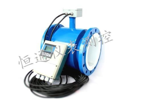
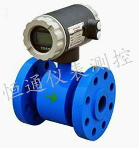
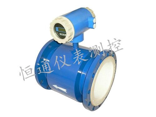
1.1 Product Description
HTMC LDE electromagnetic flow meters are intended for fluid measurement in most industries including
water, wastewater, food and beverage, pharmaceutical and chemical.
……….
There are two basic components of electromagnetic flow meter: 1)The Detector, which includes the flow
tube, isolating liner and measuring electrodes, and 2) The Converter, which is the electronic device
responsible for signal processing, flow calculation, display and output signals.
The materials of construction of the wetted parts (liner and electrodes) should be appropriate for the
specifications on the intended type of service. Review of the compatibilities consistent with the
specifications is recommended.
All electromagnetic flow meters are factory tested and calibrated. A calibration certificate is included in theshipment of each meter.
Magnetic Flowmeter Manual ‐ Hardware 3
1.2 Unpacking and Inspection
Upon receipt, examine your meter for visible damage. The meter is a precision measuring instrument and
should be handled carefully. Remove the protective plugs and caps for a thorough inspection. If any items
are damaged or missing, contact us.
Make sure the flow meter model meets your specific needs. For your future reference, it might be useful to
record this information on nameplate in the manual in case it becomes unreadable on the meter.
Transportation and Handling
Do not lift the detector from the Converter
housing, the junction box or the connecting cable.
Use lifting lugs for larger sizes is recommended.
Very large meter sizes are packed and crated with
the meter laying on its side for shipping safety
and stability reasons. In order to lift the meter in
vertical position, it's recommended to use a sling
rigged method as shown below.
If using a forklift, do not lift the detector from its
body between the flanges. The housing could be
accidentally dented and permanent damage
could be caused to the internal coil assemblies.
Warning: NEVER introduce the forklift,
chains, wire slings or any other sharp object
inside the flow tube for lifting or handling
purpose. This could permanently damage the
isolating liner and could render the meter
inoperable.
Magnetic Flowmeter Manual ‐ Hardware 4
2. TECHNICAL DATA
Measuring system
Measuring principle Faraday's law
Application range Electrically conductive fluids
Measured Value
Primary measured value Flow velocity
Secondary measured value Volume flow
Design
Features Fully welded maintenance‐free sensor
Flange version with full bore flow tube
Standard as well as higher pressure ratings
Large diameter range from DN25...3000 with
r ed liners approved for drinking water
Industry specific insertion lengths
Modular construction The measurement system consists of a flow
sensor and a signal converter. It is available as
compact and as separate version.
Compact version With 511B converter: 110‐240Vac Power
With 521B converter: 18‐36V DC Power
With W800L/W800W: Battery Power
Remote version In wall mount version with 211B converter (110‐
240Vac) or 221B converter (18‐36V DC)
With W800F converter: Battery Power
Measurement range ‐12...+12 m/s / ‐40...+40 ft/s
Measuring accuracy
Flow conditions similar to EN 29104
Medium: Water
Electrical conductivity: ≥ 300 μS/cm
Temperature: +10...+30°C / +50...+86°F
Inlet section: ≥ 5 DN
Reference conditions
Operating pressure: 1 bar / 14.5 psig
Flow Meter Accuracy Standard: 0.5% of rate
Optional: 0.2% of rate
Magnetic Flowmeter Manual ‐ Hardware 5
Operating conditions
Temperature
Hard rubber liner: ‐5...+60°C
Polypropylene liner: ‐5...+90°C
Process temperature
PTFE liner: ‐5...+120°C
Standard (with aluminum converter housing): Ambient temperature
(all versions) ‐20…+60°C (Protect electronics against self‐
heating with ambient temperatures above 55°C)
Storage temperature ‐20...+70°
Pressure
DN2200...3000: PN 2.5
DN1200...2000: PN 6
DN200...1000: PN 10
DN65...150: PN 16
DN10...50 : PN 40
EN 1092‐1
Other pressures on request
ISO insertion length Optional for DN15...600
1...24": 150 lb RF ASME B16.5
Other pressures on request
DN10...1000 / 2...40": 10 K JIS
Other pressures on request
Pressure drop Negligible
Fluid
Physical condition Conductive liquids
Electrical conductivity ≥ 5 µS/cm
Permissible gas content
(volume)
≤ 5%
Permissible solid content
(volume)
≤ 70%
Installation conditions
Installation Take care that flow sensor is always fully filled
For detailed information see chapter "Cautions
for Installation"
Flow direction Forward and reverse
Arrow on flow sensor indicates positive flow
direction.
Inlet run ≥ 5 DN
Outlet run ≥ 2 DN
Magnetic Flowmeter Manual ‐ Hardware 6
Materials
Sensor housing Sheet steel, polyurethane coated
Other materials on request
Measuring tube Austenitic stainless steel
Flanges Carbon steel, polyurethane coated
Other materials on request
Liner Standard
DN10...40: F46
DN50…300: PTFE or Hard Rubber
DN300...2200: Hard rubber
Connection box (only remote
versions)
Standard: polyurethane coated die‐cast
aluminum
Measuring electrodes Standard: Stainless steel 316L
Option: Hastelloy C, titanium, tantalum
Other materials on request
Grounding rings Standard: Stainless steel
Option: Hastelloy C, titanium, tantalum
Grounding electrodes (option) Same material as measuring electrodes.
Process connections
Flange
EN 1092‐1 DN25...3000 in PN 6...40
ASME 1…120" in 150 lb RF
JIS 25…1000 in 10...20K
Design of gasket surface RF
Other sizes or pressure ratings on request


