| Model: | - |
|---|---|
| Brand: | - |
| Origin: | Made In China |
| Category: | Industrial Supplies / Rubber & Plastics Machine |
| Label: | Hardware mould , Plastic mold , Die casting mold |
| Price: |
-
|
| Min. Order: | - |
Product Description
Dimensions and tolerances of punch and die
The dimensional accuracy of the workpiece is determined by the dimensions and tolerances of the convex and concave molds in the last drawing. Therefore, in addition to the dimensional tolerances of the last drawing dies, the dimensional tolerances of the molds for the first and middle passes and the dimensional tolerances of the drawing semi-finished products There is no need to make strict restrictions. At this time, the size of the mold should be equal to the transition size of the blank. If the die is used as the benchmark, the die size is:
The punch size is:
For the last drawing process, the dimensions and tolerances of the drawing die and punch should be determined according to the requirements of the part.
When the dimensions and tolerances of the workpiece are required, the die is used as the benchmark. First determine the size of the die because the die size gradually becomes larger with the increase in wear during deep drawing, so the die size should be smaller at the beginning. Its value is:
The punch size is:
When the internal dimensions and tolerances of the workpiece are required (as shown in Figure 4.6.9b), take the punch as the benchmark and determine the punch size first. Taking into account that the punch is basically not worn and the rebound of the workpiece, the starting size of the punch should not be too large. Its value is:
The die size is:
The manufacturing tolerance pictures and pictures of the convex and concave molds can be selected according to the tolerance of the workpiece. When the workpiece tolerance is above itl3, the pictures and pictures can be taken according to it6~8. When the workpiece tolerance is below itl4, the pictures and pictures can be taken according to itl0.
Drawing part size and die size
a) When the shape is required; b) When the inner shape is required
The structure of convex and concave molds
The structure of the drawing punch and the die depends on the shape and size of the workpiece, as well as the process requirements such as the drawing method and the number of drawing times. Different structural forms have an impact on the drawing deformation, the degree of deformation, and the quality of the product. Different influences.
When the relative thickness of the blank is relatively large, it is not easy to wrinkle, and it is not necessary to use a binder ring to press the edge, a tapered die should be used (see Figure 4.2.4). This kind of mold makes the blank in the initial stage of drawing a curved shape, so it has a greater resistance to instability than a flat-end drawing concave mold, so it can be drawn with a smaller drawing coefficient.
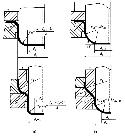
When the relative thickness of the blank is small and the blank holder must be used for multiple deep drawing, the die structure shown in Figure 4.6.10 should be used. Figure 4.6.10a The convex and concave molds have rounded corners and are used to draw the deep-drawn parts of the diameter picture. In Figure 4.6.10b, the convex and concave molds have an oblique angle structure, which is used to draw deep-drawn parts with a diameter d ≥ 100mm.
Figure 4.6.10 The structure of the working part of the drawing die
The use of this beveled convex mold and concave mold, in addition to improving the flow of metal, reducing deformation resistance, the material is not easy to thin and other general tapered concave mold characteristics, can also reduce the degree of repeated bending deformation of the blank and improve the parts The quality of the side wall makes it easy to locate the blank in the next process. Regardless of the structure used, attention should be paid to the coordination of the shape and size of the punching dies in the two previous processes, so that the shape of the semi-finished product obtained in the previous process is conducive to the forming of the subsequent process. For example, the shape and size of the blank holder should be the same as the corresponding part of the punch in the previous process, and the tapered angle picture of the deep drawing die should also be consistent with the bevel angle of the punch in the previous process, and the top of the punch in the previous process. path
The picture should be smaller than the picture of the diameter of the punch in the subsequent process to avoid unnecessary repeated bending of the blank in part a, which will deteriorate the quality of the workpiece cylinder wall, etc. (Figure 4.6.11).
Figure 4.6.11 Bevel size confirmation
Figure 4.6.12 The change of the size of the blank bottom step in the final drawing
In order to make the bottom of the part flat after the last drawing, if it is a punch with a rounded structure, the center of the corner radius of the last drawing punch should be located at the same line as the center of the second penultimate drawing punch’s corner radius. Center line. If it is an oblique die structure, the oblique line at the bottom of the punch in the penultimate process (picture channel) should be tangent to the fillet radius of the last punch, as shown in Figure 4.6.12.
The cone angle pictures of the punch and the die have a certain effect on deep drawing. A large picture is good for drawing deformation, but when the picture is too large, a relatively small material may cause wrinkles, so the size of the picture can be determined according to the thickness of the material. Generally, when the material thickness is 0.5--1.0mm; when the material thickness is 1.0~2.0mm
In order to facilitate the removal of the workpiece, the drawing punch should be drilled with vent holes, as shown in Figure 4.6.10. Its dimensions can be found in Table 4.6.4.
Table 4.6.4 Air vent size
Shenda Kaituo's main molds include automobile molds, screw molds, gear molds, fan blade molds, die-casting molds, electronic and electrical molds, two-color three-color molds, and laminated molds. The size ranges from 0.5MM spare parts to 17 tons of complete large molds.
Shunqiang Electronics-Hardware molds, the continuous mold sounds, gold is amazing!
Member Information
| Huizhou Shunqiang Electronics Co., Ltd | |
|---|---|
| Country/Region: | Guang Dong - China |
| Business Nature: | Manufacturer |
| Phone: | 13715334662 |
| Contact: | Kennethchui (Engineer) |
| Last Online: | 23 Mar, 2025 |
