| Model: | - |
|---|---|
| Brand: | - |
| Origin: | Made In China |
| Category: | Industrial Supplies / Machine Hardware / Mold |
| Label: | Hardware mould , Plastic mold , Die casting mold |
| Price: |
-
|
| Min. Order: | - |
Product Description
The design of hydraulic clamps is a process of continuous improvement. This time we share two patented solutions, namely the detailed design and analysis of the three-point centering hydraulic clamps for the flywheel housing and the gear cover hydraulic clamps.
1. Three-point centering hydraulic clamp for flywheel shell
In response to the problem:
At present, the centering structure of the 10-sequence machining fixture for the flywheel shell adopts a centering structure of two fixed guide wheels and one spring floating guide wheel. Due to the different casting batches of the workpiece blanks, the size deviation of the workpiece blanks is large, which leads to a large deviation between the hole center of the workpiece positioning and the fixture positioning center. The fixture does not play a centering role, resulting in holes in the subsequent processing workpieces. The wall thickness is uneven, the deviation is too large, and the waste product appears.
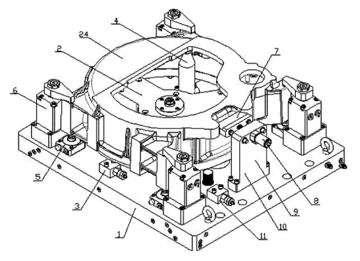
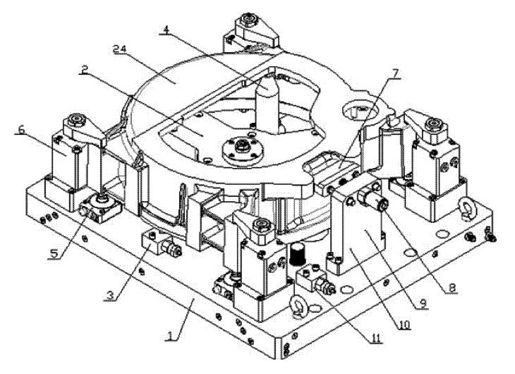
Figure 1 Flywheel shell three-point centering hydraulic clamp
1. Fixture bottom plate 2. Three-point centering assembly 3. Sequence valve 4. Support column
5. Support cylinder 6. Angle cylinder 7. Angle positioning block 8. Pull cylinder
9. Vertical plate 10. Angular positioning component 11. Sequence valve 24. Workpiece
Technical solutions:
In order to overcome the above shortcomings, a three-point centering hydraulic clamp for the flywheel shell is designed. Three evenly distributed guide rods are pushed by the push cylinder to center the positioning head on the guide rod.
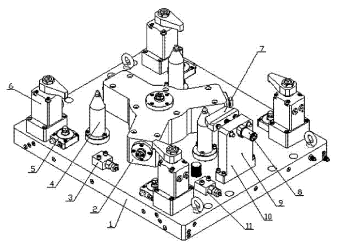
Figure 2 Schematic diagram of fixture structure
1. Fixture bottom plate 2. Three-point centering assembly 3. Sequence valve 4. Support column
5. Support cylinder 6. Angle cylinder 7. Angle positioning block 8. Pull cylinder
9. Vertical plate 10. Angular positioning component 11. Sequence valve
Technical features:
The flywheel shell three-point centering hydraulic fixture, in turn includes the fixture bottom plate, three-point centering assembly, sequence valve a, sequence valve b, support column, support cylinder, corner cylinder and angular positioning assembly and other components. The three-point centering component is set on the bottom plate of the fixture. The positioning heads are on the same arc by adjusting the adjustment pads, and three evenly distributed guide rods are pushed by the push cylinder to center the positioning heads on the guide rods. The sequence valve, the support column, the support cylinder, and the corner cylinder are arranged on the bottom plate of the fixture. The angular positioning component is arranged on the bottom plate of the fixture, and the pulling cylinder is arranged on the vertical plate to be connected with the angular positioning block.
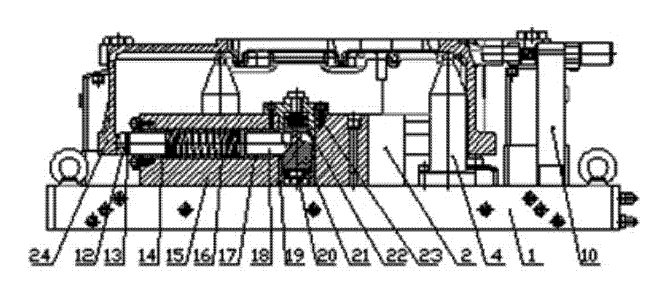
Figure 3 Side sectional view of the fixture
1. Fixture base plate 2. Three-point centering assembly 4. Support column 10. Angular positioning assembly
12. Positioning head 13. Adjusting pad 14. Positioning guide sleeve 15. Three-point positioning seat
16. Spring 17. Bush 18. Guide rod 19. Centering sleeve 20. Push cylinder
21. Push rod 22. Spring 23. Thrust flange 24. Workpiece
Use process:
Place the workpiece on the support column according to the angular positioning direction. At this time, the solenoid valve of the hydraulic station is in the middle position for unloading, and the angular positioning block is inserted into the notch on the workpiece for positioning. After the oil is ventilated in the oil circuit, the push cylinder in the three-point centering assembly pushes the push rod to move the positioning head on the guide rod to contact the positioning surface of the workpiece to achieve three-point centering positioning. Then through the sequence valve, the support cylinder is raised and fixed. Then through the sequence valve, the corner cylinder presses the workpiece tightly. After the workpiece is processed, the pressure of the oil circuit is relieved. At this time, the pull cylinder in the angular positioning assembly pulls the angular positioning block back and separates from the workpiece. In the three-point centering assembly, the push cylinder retreats, the push rod retreats under the action of the spring, and the guide rod drives the positioning head to retreat under the action of the spring, and the positioning head is separated from the workpiece.
2. Gear cover hydraulic clamp
In response to the problem:
At present, the gear cover is processed by positioning the large hole of the workpiece blank, processing the upper plane and the hole, and then selecting the processed two holes for positioning and punching the blank. Two sets of fixtures are required to complete the process, and the cost of the process is relatively high.
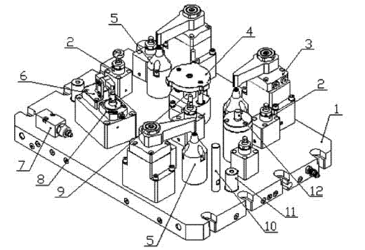
Figure 4 Schematic diagram of the hydraulic clamp structure of the gear cover
1. Fixture plate 2. Auxiliary support cylinder 3. Corner cylinder 4. Positioning plate assembly
5. Support column 6. Lever cylinder 7. Sequence valve 8. Support cylinder
9. Pull cylinder 10. Thick positioning rod 11. Latch pin 12. Elastic positioning pin
Technical solutions:
Design a kind of gear cover hydraulic clamp, use the large hole of the workpiece blank as the positioning hole, and process the large hole in this sequence. The large hole positioning of the workpiece blank is composed of a positioning plate assembly and a pulling cylinder. After the workpiece is positioned and clamped, the pulling cylinder pulls the positioning plate out of the positioning hole, and at the same time the auxiliary supporting cylinder is lifted and clamped.
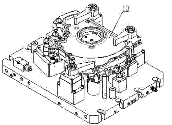
Figure 5 Gear cover hydraulic clamp with workpiece
Technical features:
The pull cylinder is set in the positioning plate assembly; the auxiliary support cylinder, corner cylinder, positioning plate assembly, support column, lever cylinder, sequence valve, support cylinder, coarse positioning rod, bolt and elastic positioning pin assembly and other components are set on the fixture plate ; The sequence valve controls the pull-down and clamping of the pulling cylinder, the lever cylinder and the auxiliary cylinder; the bolt controls the position of the fixture plate and the worktable.
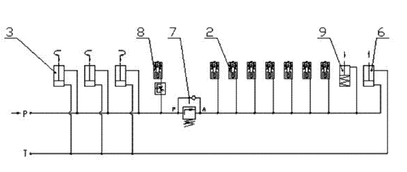
Figure 6 Hydraulic principle diagram of gear cover hydraulic clamp
2. Auxiliary support cylinder 3. Angle cylinder 6. Lever cylinder
7. Sequence valve 8. Support cylinder 9. Pull cylinder
Use process:
Place the workpiece on the support column along the thick positioning rod on the fixture plate, insert the hole on the workpiece into the positioning plate assembly and the elastic positioning pin assembly; the corner cylinder clamps the workpiece, while the support cylinder clamps, through the sequence valve, The lever cylinder is clamped, and the auxiliary supporting cylinder is lifted and clamped, and at the same time, the pulling cylinder pulls down the positioning plate on the positioning plate assembly to separate the workpiece.
Member Information
| Huizhou Shunqiang Electronics Co., Ltd | |
|---|---|
| Country/Region: | Guang Dong - China |
| Business Nature: | Manufacturer |
| Phone: | 13715334662 |
| Contact: | Kennethchui (Engineer) |
| Last Online: | 01 Aug, 2024 |
Related Products of this Company
-
A kind of high elastic spring-related
-
12 sets of mold structure diagram
-
Automobile air conditioner shell mould
-
Metal mold stamping process
-
What are the acceptance criteria for a
-
New insert type spring clamp chuck
-
Mold vacuum heat treatment technical
-
Technical knowledge of plastic molds
-
3 sets of classic mold structure
-
9 design cores for stamping die!
